Machine equipped with a temperature compensated lathe spindle

a technology of temperature compensation and lathe, which is applied in the direction of electric controllers, programmers, instruments, etc., can solve the problems of impairing machining precision, large amount of heat generation, and high machining precision, etc., to achieve the effect of reducing the number of parts

Inactive Publication Date: 2005-10-25
WALTER MASCHINENBAU GMBH
View PDF11 Cites 15 Cited by
  • Summary
  • Abstract
  • Description
  • Claims
  • Application Information

AI Technical Summary

Benefits of technology

[0005]The inventive concept is fundamentally applicable to any machine for cutting-type machining of a workpiece. It is especially advantageously applicable in a grinding machine that is additionally set up for electroerosive machining. While electroerosive machining takes place at relatively low rpm, for instance 200 rpm, and generates only relatively little heat at the tool, a grinding operation takes place at substantially higher rotary speeds, for instance of 3000 rpm, and with direct contact between the tool and the workpiece, and as a result a relatively large amount of heat is generated. The detection and compensation of the temperature of the shaft creates especially high machining precision in this case.
[0006]Detecting the temperature at the shaft is preferably done via a radiation-sensitive temperature sensor in contactless fashion. Contactless detection makes it possible to measure the temperature quickly and precisely, even during machine operation. The sensor is preferably oriented such that a portion of the shaft completely occupies its detection region. The radiation-sensitive sensor thus detects the mean temperature of a cylindrical portion of the shaft. The shaft portion picked up by the sensor is preferably located between the work tool and a bearing device that determines the axial position of the shaft. As a result, the sensor detects the precise region of the shaft whose change in length, if not compensated for, would impair the machining precision.
[0007]In an advantageous embodiment, at least two temperature sensors are provided, which detect the temperature of the shaft on both sides of the axially fixed bearing device. This embodiment has the advantage that the shaft can carry at least one tool on both ends, and both shaft portions, of different lengths, can be compensated for in terms of their temperature expansion. There is also the advantage that if both sensors show different temperatures, the conclusion can be drawn that there is a distribution of temperature in the shaft, making it possible to compensate for the change in length even more precisely. In the simplest case, this can be done by means of a linear approximation, for instance. If both sensors show the same temperature, it is assumed that the entire shaft is at a uniform (elevated) temperature. Based on this assumption, the measured temperature values are then used for calculation or other determination of the increase in length that occurs and that needs to be compensated for. However, if one sensor for instance shows a higher temperature while the other sensor shows a lower temperature, it can be assumed that along the shaft a temperature drop prevails, which for instance is constant, and the change in length can then be calculated or determined on the basis of this temperature drop.
[0008]It has been found advantageous to provide at least one of the shaft portions that are located in the detection region with a low-reflection surface, for instance a surface coating. For example, the shaft can be burnished. This averts interfering light reflections and makes secure temperature detection possible. It is possible to burnish either a cylindrical region or the entire shaft, as well as to provide the shaft with a matte, blackened, burnished or otherwise-coated surface in only some regions. For instance, longitudinal strips can be attached to the shaft that pass through the viewing field (detection region) of the sensor when the shaft rotates.
[0009]This has the advantage that the sensors output an alternating signal whose amplitude is a measure for temperature. Thus direct components and drifting effects, occurring from aging or temperature change of the sensor itself, are filtered out in a simple way.
[0010]In addition, the machine can be provided with temperature sensors on the detection region, in order to detect and compensate for temperature changes in the detection region. In conjunction with the temperature compensation of the shaft, especially high precision is attained.

Problems solved by technology

As a result, the sensor detects the precise region of the shaft whose change in length, if not compensated for, would impair the machining precision.

Method used


Image

  • Machine equipped with a temperature compensated lathe spindle
  • Machine equipped with a temperature compensated lathe spindle
  • Machine equipped with a temperature compensated lathe spindle

Examples


Embodiment Construction

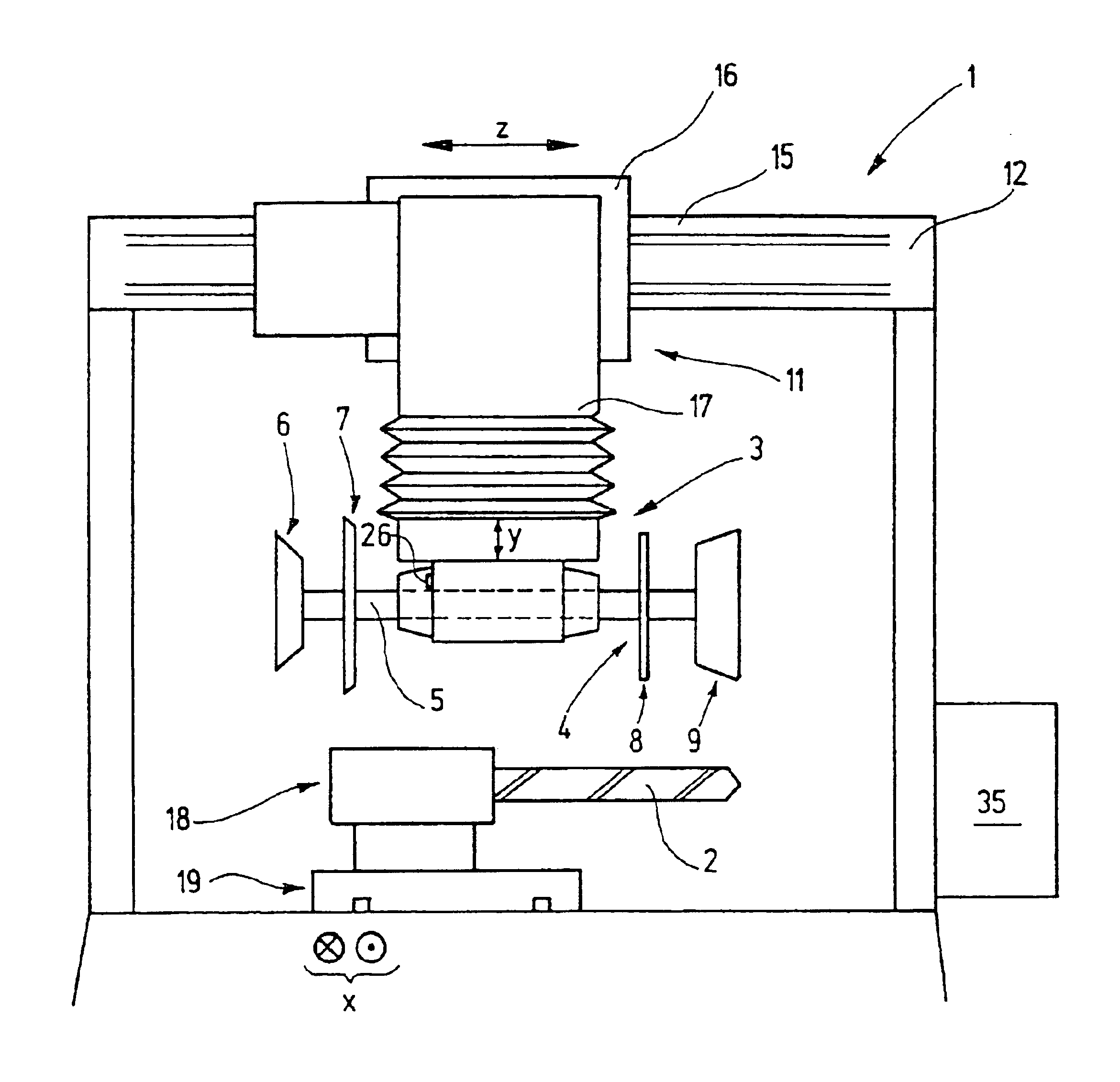
[0018]In FIG. 1, a machine 1 embodied as a grinding machine is shown; it is used to machine tools 2, such as drills, milling cutters, and the like. Thus in the present situation, the tools 2 are the workpieces. For machining them, in the machine shown as an example here, a combined grinding and erosion head 3 is used, which has a work spindle 4. A shaft 5, which carries tools 6, 7, 8, 9, belongs to the work spindle. The tools 6, 7, 8, 9 can be grinding tools, erosion tools, or the like.

[0019]The grinding and erosion head 3 is held via a positioning device 11 on a machine frame 12. By way of example, a horizontal positioning device 14, which is formed by a horizontal guide 15, a carriage 16 supported on it, and an associated drive device, belongs to the positioning device 11. The horizontal positioning device 14 serves to position the grinding and erosion head 3 in the Z direction.

[0020]The carriage 16 carries a vertical positioning device 17, to which in turn a guide in a drive mech...


PUM


Abstract

A machine for machining a workpiece with at least one revolving or rotating tool has a work spindle with a shaft (5), whose temperature is monitored by means of at least one temperature sensor (26). The temperature sensor is detected in contactless fashion. The sensor (26) is preferably a radiation-sensitive sensor, which detects the temperature radiation output. by the shaft (5). In triggering the positioning drive mechanisms, the control unit (35) of the machine (1) takes into account the temperature expansions of the shaft (5) that result from the temperature changes in the shaft. The positioning drive mechanisms serve to position a tool (6), carried by the shaft (5), relative to the workpiece (2). A machining precision is thus achieved that is independent of the temperature and temperature changes of the machine (1) overall, of temperature changes in the coolant—lubricant, and of temperature changes in the tool (6) and the shaft (5), that can all be caused by the power converted at the machining site.

Description

BACKGROUND[0001]The invention relates to a machine for machining a workpiece with a revolving or rotating tool.[0002]For precision machining of workpieces, such as for grinding, it is necessary that a grinding tool held on a work spindle be positioned with a precision equivalent to the desired precision of the outcome of the work. As a rule, the work spindle is supported on a machine frame via one or more positioning devices. The positioning devices detect the position of the work spindle. To preclude inaccuracies in the positioning that can be caused by temperature changes of the machine frame, machine frames are sometimes provided with temperature sensors, whose signals are taken into account by a control unit that serve to trigger the positioning drive mechanisms. However, this does not make it possible to detect inaccuracies that result from a temperature change between the engagement point of the tool, such as the grinding tool, and the fixed bearing of the work spindle. In tho...

Claims


Application Information

Patent Timeline
Patent Type & Authority Patents(United States)
IPC IPC(8): B23Q17/22B23Q1/70B23Q11/00B23Q1/00B23Q15/18
CPCB23Q1/70B23Q11/0007B23Q17/22B23Q15/18
Inventor ENGELFRIED, THOMAS
Owner WALTER MASCHINENBAU GMBH
Why Eureka
Try Eureka