Grating device with high diffraction efficiency

a grating device and high diffraction efficiency technology, applied in the field of optical gratings, can solve the problems of limiting the useful life of the grating, low diffraction efficiency, and substantial replacement costs, and achieve the effect of high diffraction efficiency and high wavelength dispersion

Inactive Publication Date: 2005-10-25
LUMELLA
View PDF1 Cites 67 Cited by
  • Summary
  • Abstract
  • Description
  • Claims
  • Application Information

AI Technical Summary

Benefits of technology

[0012]The invention is directed to an efficient grating device operating away from the blaze angle in a low order with high diffraction efficiency and high wavelength dispersion.

Problems solved by technology

The disadvantage of the echelle gratings is their low damage threshold to laser radiation which limits their useful service life, and their low diffraction efficiency at steep angles of incidence (in the order of 78°), resulting in substantial replacement costs.
In some cases, original holographic gratings are used where the groove structure is formed in photo-active materials such as photoresist, however, this type of grating is difficult to overcoat with dielectric materials since it cannot withstand the high temperatures required to make a durable multilayer dielectric.
However, none of the references suggests that the diffraction efficiency of ruled gratings, such as symmetric triangular gratings, can be increased by, for example, an order of magnitude, at wavelengths where the efficiency of uncoated or metal-layer coated gratings is so low as to render the gratings useless.

Method used


Image

  • Grating device with high diffraction efficiency
  • Grating device with high diffraction efficiency
  • Grating device with high diffraction efficiency

Examples


Embodiment Construction

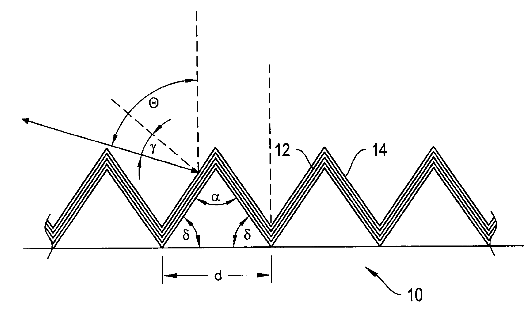
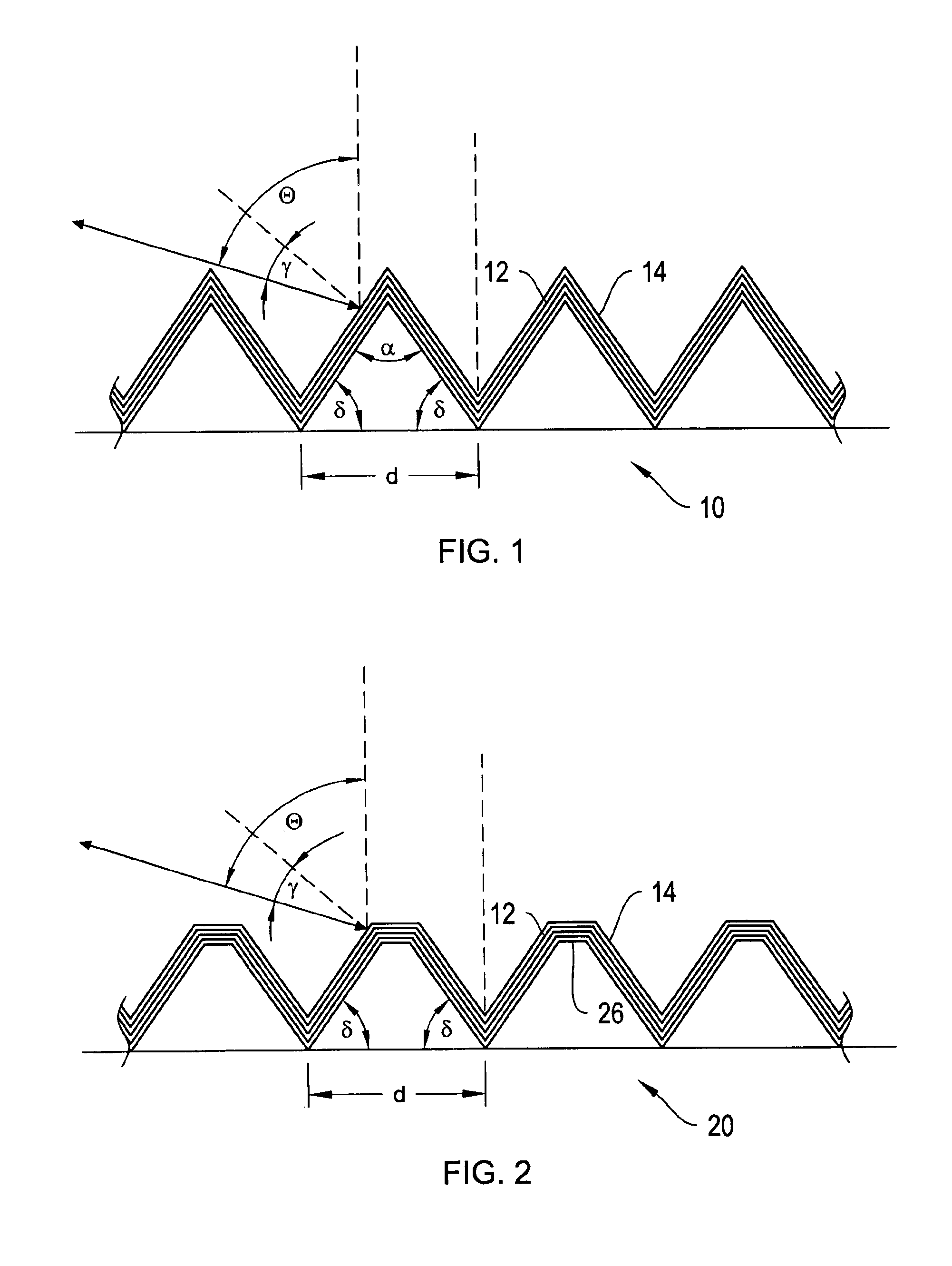
[0023]The invention is directed to gratings that operate efficiently in low order and at large diffraction angles different from the blaze angle, and more particularly to dielectric-stack coated diffraction gratings operating in Littrow configuration. Such gratings are useful for providing feedback in lasers

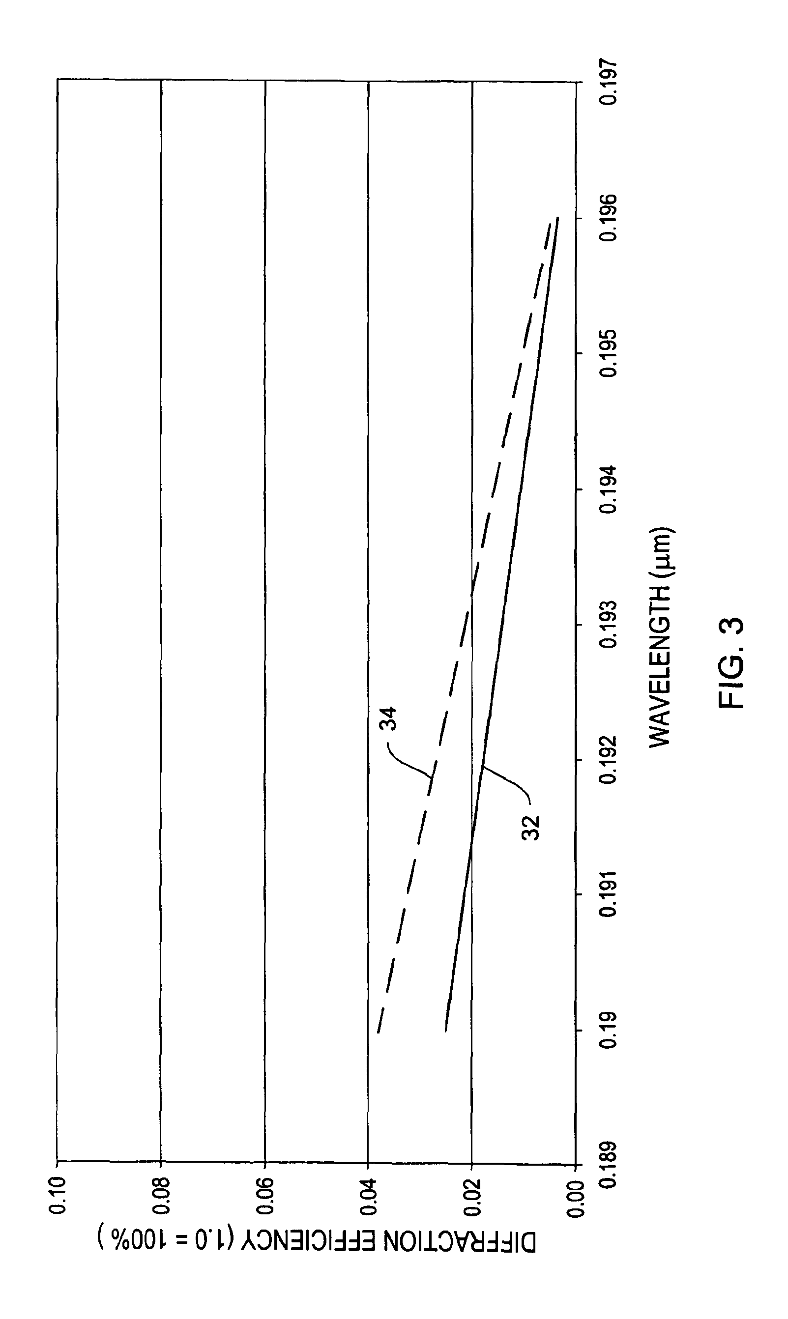
[0024]Referring first to FIG. 6, a conventional laser cavity 60 includes a laser gain medium 62 that can be electrically or optically pumped. The pump is not shown. Optical feedback is provided by a partially reflecting output coupling mirror 64 and a wavelength tuning element 66, for example, a diffraction grating operating in Littrow configuration. As mentioned above, modern lithography tools expose, for example, photoresist to render feature sizes with linear dimensions of less than 0.1 μm, using excimer laser emitting at a wavelength of, for example, 193 nm or 248 nm.

[0025]Laser cavities that employ diffraction gratings as the wavelength tuning element suffer from low efficie...


PUM


Abstract

A grating structure with a dielectric coating is disclosed that operates efficiently away from the blaze angle in low order with a high diffraction efficiency and high wavelength dispersion. Such grating structure can be employed in Littrow configuration to provide, for example, cavity feedback in excimer lasers.

Description

FIELD OF THE INVENTION[0001]The invention relates to optical gratings, and more particular to an efficient grating device operating away from the blaze angle in low order with a high diffraction efficiency and high wavelength dispersion.BACKGROUND OF THE INVENTION[0002]Excimer lasers operating at 193 nm and 248 nm are increasingly used as light sources for mask exposure in semiconductor manufacturing to decrease the feature size of integrated circuits. This allows more circuit elements per circuit area and increases wafer throughput in the factory thus reducing overall costs. To further enhance the rendition of the mask features, the lasers line is narrowed to produce very narrow spectral ranges, typically 10 picometers or less. Diffraction gratings, in particular echelle gratings are used to this end. The disadvantage of the echelle gratings is their low damage threshold to laser radiation which limits their useful service life, and their low diffraction efficiency at steep angles ...

Claims


Application Information

Patent Timeline
Patent Type & Authority Patents(United States)
IPC IPC(8): G02B5/18
CPCG02B5/1809G02B5/1861
Inventor HOOSE, JOHNFRANKEL, ROBERTPOPOV, EVGENYNEVIERE, MICHEL
Owner LUMELLA
Why Eureka
Try Eureka