
Optical head with GRIN lens

a technology of optical head and lens, applied in the field of optical head, can solve the problems of reduced access speed, difficult to implement the above-described optical system in a miniature, and limited material suitable for it, so as to achieve easy assembly, reduce light loss, and simple configuration

Inactive Publication Date: 2005-10-25
SAMSUNG ELECTRONICS CO LTD
View PDF7 Cites 3 Cited by
  • Summary
  • Abstract
  • Description
  • Claims
  • Application Information

AI Technical Summary

Benefits of technology

The present invention provides an optical head with a simple structure that can access data at high speeds. It includes a slider, a GRIN lens, and a light-emitting unit. The GRIN lens focuses a light spot on a recording layer with high efficiency. The optical head is easy to manufacture and can access data on a recording layer with high precision. The GRIN lens has a unique structure that allows for high-speed data access and easy assembly. The optical head is compact and light-weight.

Problems solved by technology

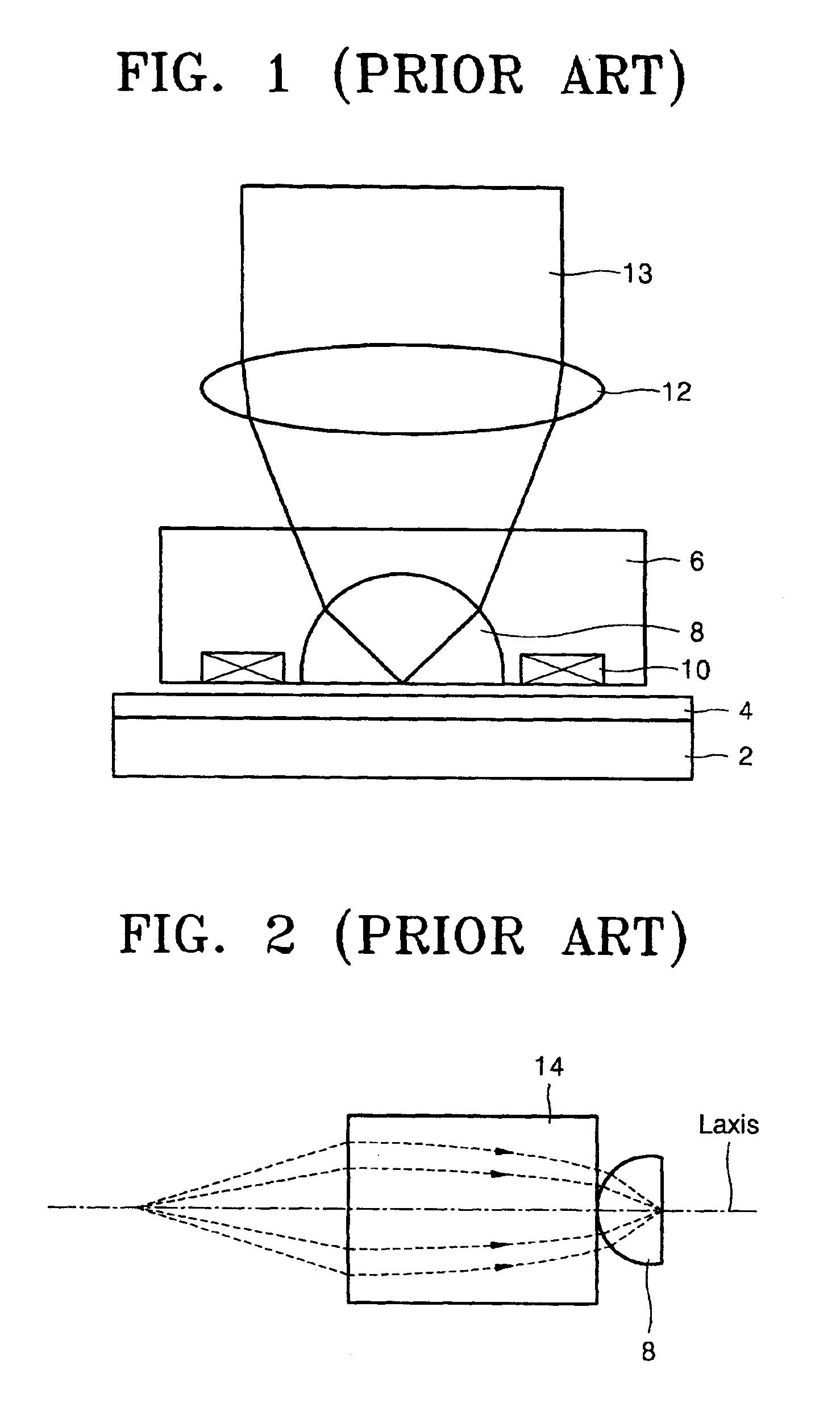
The conventional optical head shown in FIG. 1, which uses both the objective lens 12 and the SIL 8, also has a problem of access speed reduction due to its increased volume and weight.
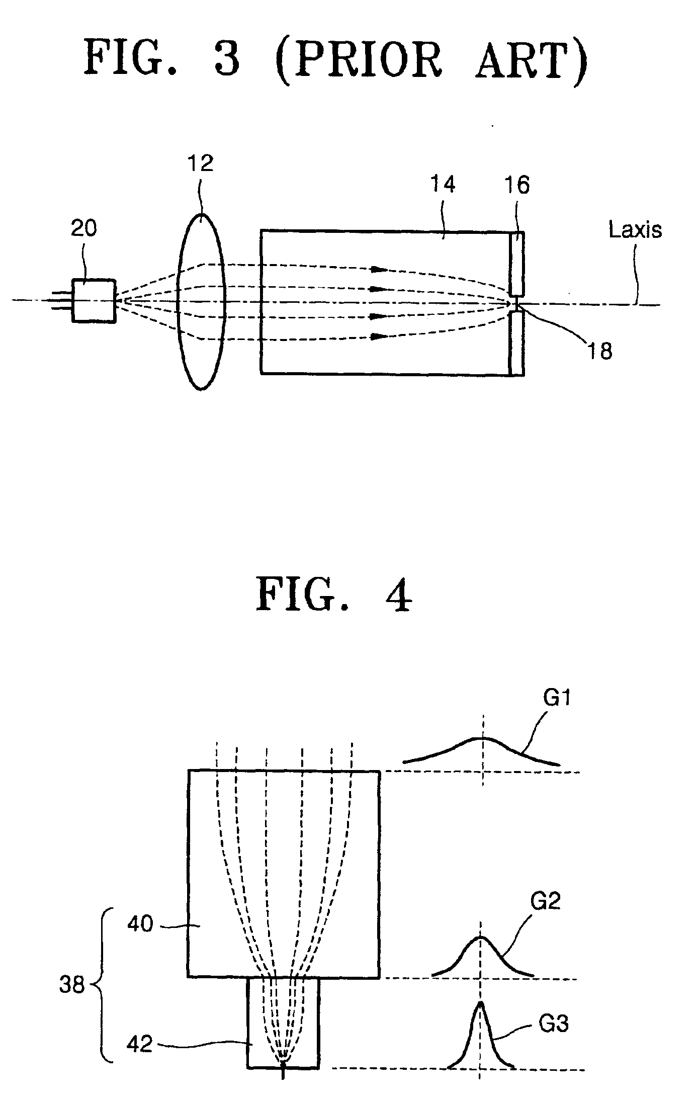
However, this optical system still needs a coaxial alignment between the GRIN lens 14 and the SIL 8, and it is difficult to implement the above described optical system in a miniature, light-weight optical head.
Although a slit of a desired size can be formed by partially melting and vaporizing the metal layer 16, suitable materials therefor, which have low reflectance, high absorbance, and low melting point, are extremely limited.
In this aspect, the optical head shown in FIG. 3 is unsuitable for practical use in the field due to its poor optical efficiency.

Method used


Image

  • Optical head with GRIN lens
  • Optical head with GRIN lens
  • Optical head with GRIN lens

Examples


embodiment 1

[0051]Illustrative, Non-limiting, Embodiment 1

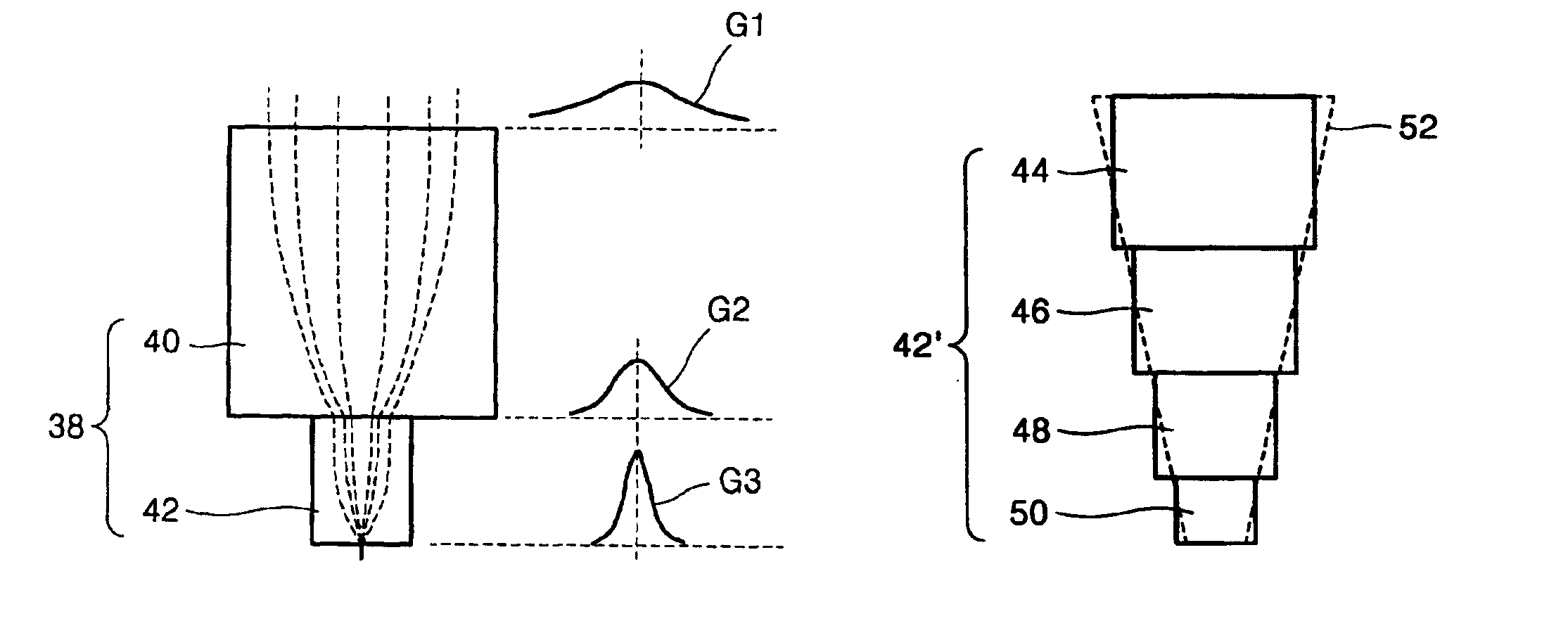
[0052]Referring to FIG. 6, reference numeral 54 denotes a slider of an optical head. A GRIN lens (see FIG. 4) composed of the first and second GRIN lenses 40 and 42 is formed in the middle of the slider 54. The second GRIN lens 42 protrudes from the exit surface of the first GRIN lens 40. A recording layer of an optical disk (not shown) is positioned in the vicinity of the bottom surface of the slider 54. Preferably, the second GRIN lens 42 protrudes to an extent to be coplanar with the bottom surface of the slider 54.

[0053]When the optical head approaches the optical disk for data recording, the spacing between the recording layer of the optical disk and the slider 54 is maintained to be less than the wavelength of a laser beam for recording, for example, about 20 nm, which is the same as the spacing between the second GRIN lens 42 and the recording layer. The thin layer of air between the second GRIN lens 42 and the recording layer all...

embodiment 2

[0055]Illustrative, Non-limiting, Embodiment 2

first embodiment

[0056]the optical head (FIG. 6) according to the present invention includes a semiconductor laser diode (not shown) for laser radiation onto the entry surface of the first GRIN lens 40. The semiconductor laser diode is spaced apart a predetermined distance from the entry surface of the first GRIN lens 40.

[0057]According to a second embodiment of the optical head, as shown in FIG. 7, (1) a heat sink 56 is provided on the slider 54, above the first GRIN lens 40, and (2) a semiconductor laser diode 58 is provided on the heat sink 56. Similar to the first embodiment, however, the second GRIN lens 42 of the second embodiment may be replaced by the GRIN lens 42′ or the tapered GRIN lens 52 shown in FIG. 5A.


PUM

PropertyMeasurementUnit
lengthaaaaaaaaaa
wavelengthaaaaaaaaaa
distanceaaaaaaaaaa

Abstract

An optical head in which a graded index (GRIN) lens is provided. The optical head includes a slider connected to an arm and flying a predetermined distance above a recording layer for data recording, a GRIN lens mounted in the slider for focusing an incident beam to form a light spot of a predetermined size on its exit surface adjacent to the recording layer, and a light-emitting unit for emitting the incident light to the GRIN lens.

Description

BACKGROUND OF THE INVENTION[0001]This application is based on Korean Patent Application No. 2001-43505 filed Jul. 19, 2001, the disclosure of which is incorporated herein by reference in its entirety.[0002]1. Field of the Invention[0003]The present invention relates in general to an optical head, and more particularly to an optical head with a graded index (GRIN) lens.[0004]2. Description of the Related Art[0005]Optical pickups for recording data in or reading data from a high-density data storage medium, such as an optical disk, include a head for recording a predetermined data in a recording layer of the data storage medium or reading the data from the recording layer using a laser beam emitted from a laser diode.[0006]The data recording density of a high-density data storage medium such as an optical disk is dependent on the spot size of a laser focused on the recording layer of the storage medium. The spot size depends upon the wavelength of a laser emitted from a laser diode fo...

Claims


Application Information

Patent Timeline
Patent Type & Authority Patents(United States)
IPC IPC(8): G11B11/24G11B7/12G11B7/122G11B7/125G11B7/135G11B7/1372G11B7/1374G11B7/1387
CPCB82Y10/00G11B7/1374G11B7/1387G11B7/122G11B2007/13727G11B11/24
Inventor LEE, MYUNG-BOKNIKOLAI, PETROVWOO, GI-MYUNG
Owner SAMSUNG ELECTRONICS CO LTD
Learn More