Polarization scrambler and optical network using the same

a scrambler and optical network technology, applied in multiplex communication, wavelength-division multiplex systems, instruments, etc., can solve the problems of hindering an increase in the spectrum density of wdm signals, reducing the received optical power, and significantly degrading the signal to noise ratio (snr), so as to suppress the spread of optical spectrum, suppress the jitter of modulated signal light, and suppress the effect of optical spectrum

Inactive Publication Date: 2005-10-25
NIPPON TELEGRAPH & TELEPHONE CORP
View PDF16 Cites 24 Cited by
  • Summary
  • Abstract
  • Description
  • Claims
  • Application Information

AI Technical Summary

Benefits of technology

[0044]As described above, the polarization scrambler of the present invention can zero the DOP in scrambled light, while causing temporal overlapping between optical pulses each of which is polarized orthogonally to the succeeding pulse. It can also generate polarized scrambled light with the spread of an optical spectrum suppressed.
[0045]Furthermore, when a polarization-dependent optical intensity modulator is used as an optical intensity modulator that modulates scrambled light transmitted via an optical fiber, the optical network of the present invention can extract a clock electric signal corresponding to a value n times (n is a natural number) as large as the value of frequency of the electric signal driving the polarization scrambler. Consequently, the phase of the data signal bit rate clock input to the polarization-dependent opt

Problems solved by technology

In particular, a decrease in received optical power causes Signal to Noise Ratio (SNR) to be significantly degraded.
This hinders an increase in the spectrum density of WDM signals.
However, if there is no temporal overlapping between optical pulses each of which is polarized orthogonally to the succeeding pulse, scrambled light has reduced power.
However, the EA modulator may suffer a heavy transmission loss, so that if it is used to construct the above described optical network, the SNR of a received signal is significantly degraded.
As a result, it is impossible to expect manufacturing costs to be successfully reduced on the basis of mass production.
However, the above described optical network does not allow the use of a polarization-dependent optical intensity modulator for the previously described reason.
This is disadvanta

Method used


Image

  • Polarization scrambler and optical network using the same
  • Polarization scrambler and optical network using the same
  • Polarization scrambler and optical network using the same

Examples


third embodiment

(Third Embodiment)

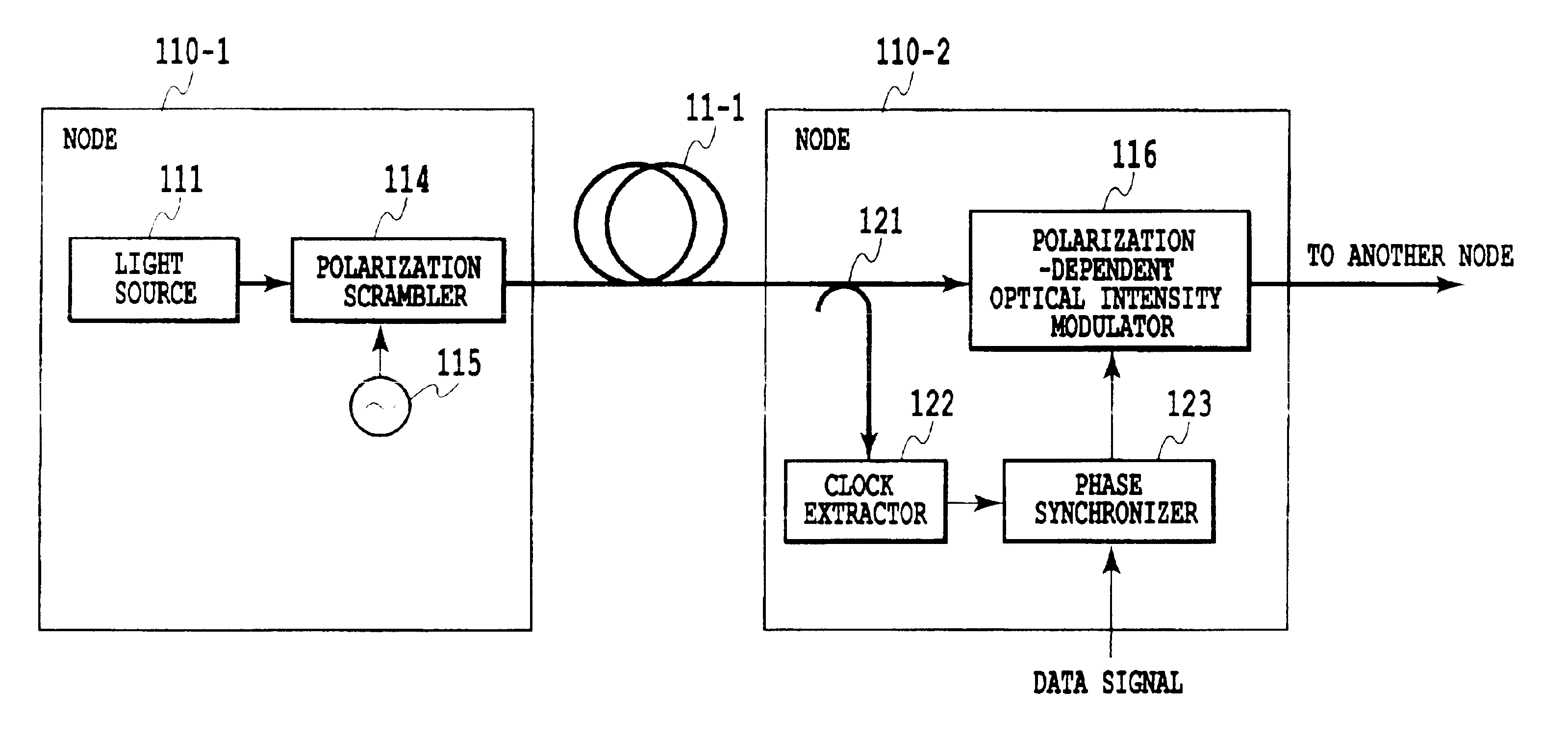
[0136]FIG. 18 shows a third embodiment of the first optical network of the present invention. The present embodiment is characterized in that at the node 110-2 according to the second embodiment, the optical splitter 121 is provided in front of the polarization-dependent optical intensity modulator 116 and a photodetector 125 converts signal light from the optical splitter into an electric signal so that a clock extractor 126 extracts a clock electric signal. The configuration of the node 110-1 is similar to that in the first embodiment.

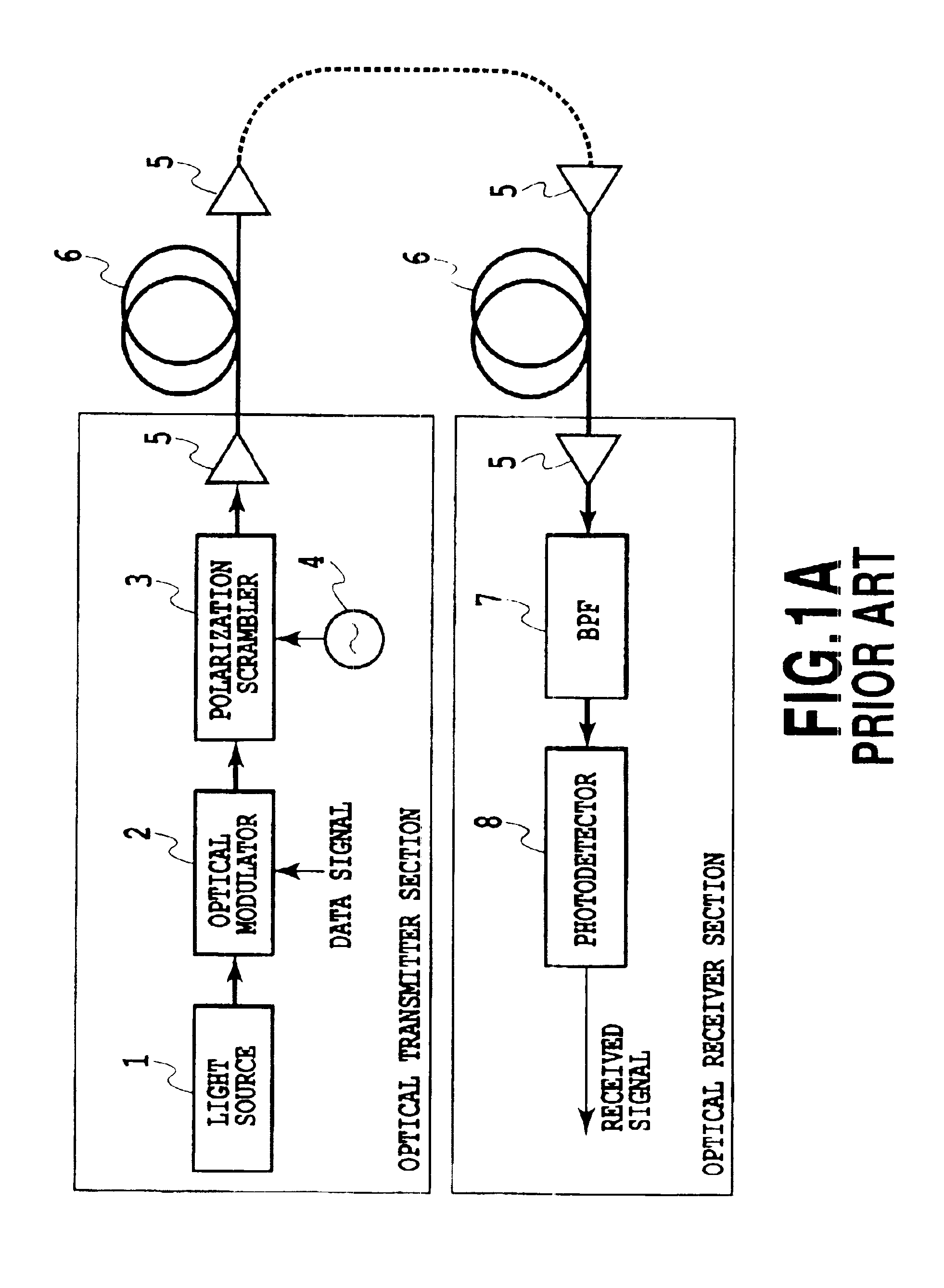
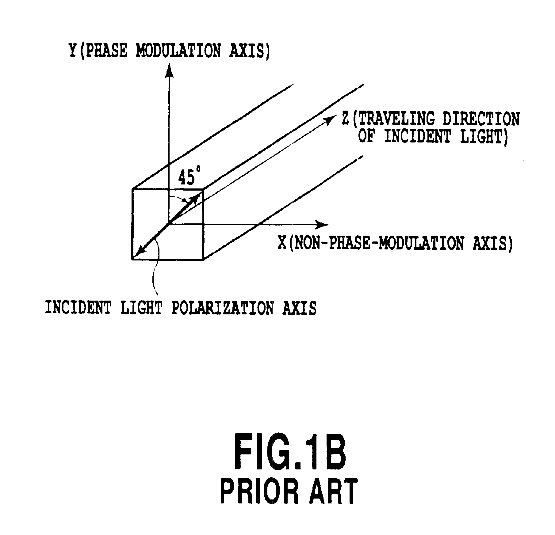
[0137]With this configuration, even if a polarization scrambler without any temporal variations in intensity, e.g. the one shown in FIGS. 1A-1B and 3A-3C and using phase modulation is used, an output from the polarization-dependent optical intensity modulator 116 has its intensity modulated (this intensity modulation is different from that carried out by a data signal) owing to its polarization dependency. As a result, a clock elect...

fourth embodiment

(Fourth Embodiment)

[0138]FIG. 19 shows a fourth embodiment of the first optical network of the present invention. The present embodiment is characterized in that at the node 110-2 according to the second embodiment, a polarizer 127 is inserted between the optical splitter 121 and the photodetector 125 so that the photodetector 125 can convert scrambled light from the optical splitter 121 preceding the polarization-dependent optical intensity modulator 116, into an electric signal and so that the clock extractor 126 can then extract a clock electric signal. The polarizer 127 allows single polarization of the scrambled light to pass through. Accordingly, output light from the polarizer 127 is always subject to intensity modulation according to the frequency of the scrambled light. Consequently, even if for example, the polarization scrambler shown in FIGS. 1A-1B and 3A-3C and using phase modulation is used, a clock electric signal can be extracted easily from an output electric signal...

fifth embodiment

(Fifth Embodiment)

[0139]FIG. 20 shows a fifth embodiment of the first optical network of the present invention. According to the present embodiment, at the node 110-2 according to the fourth embodiment, by limiting the configuration of the polarization scrambler 114, a clock electric signal can be extracted using the photodetector 125 and the clock extractor 126 and without using the polarizer 127. An example of configuration of the polarization scrambler 114 used in this embodiment will be shown below.

(First Example of Configuration of Polarization Scrambler)

[0140]FIGS. 21A, 21B, and 21C show an example of configuration of the polarization scrambler 14 according to the fifth embodiment.

[0141]In these figures, the polarization scrambler 114 is composed of an optical intensity modulator 131 that modulates a CW from the light source 111 using a sinusoidal signal from the oscillator 115, an optical splitter 132 that splits each output optical pulse from the optical intensity modulator ...


PUM


Abstract

To generate light with the degree of polarization zeroed and the spread of an optical spectrum suppressed even with temporal overlapping between optical pulses each of which is polarized orthogonally to the succeeding pulse, a polarization scrambler includes an optical pulse generator that generates optical pulses with an intensity waveform repetition period T/2 and an electrical field repetition period T in which the same intensity waveform is repeated every repetition period T/2 and in which phase is inverted every repetition period T/2, and an orthogonal polarization delay unit which receives each of the optical pulses, separates the optical pulse into two optical pulses with orthogonal states of polarization, and relatively shifts the temporal position of one of the two optical pulses from that of the other optical pulse by (2n−1)T/4 (n is a natural number) to generate light in which each pulse is polarized orthogonally to a succeeding pulse.

Description

[0001]This application claims priority from Japanese Patent Application Nos. 2002-045956 filed Feb. 22, 2002, 2002-104254 filed Apr. 5, 2002 and 2002-214849 filed Jul. 24, 2002, which are incorporated hereinto by reference.BACKGROUND OF THE INVENTION[0002]1. Field of the Invention[0003]The present invention relates to a polarization scrambler that makes the degree of polarization(DOP) of optical carrier zero. For long-haul optical amplifier transmission system, much attention is paid to polarization scrambling in which to improve degradation of transmission performance caused by the polarization dependent gain (PDG) in optical amplifiers, a transmitter scrambles the state of polarization (SOP) of optical carrier for depolarization.[0004]Furthermore, the present invention relates to an optical network configured to input a continuous wave (CW) transmitted via an optical fiber from a light source arranged at one node, to an optical intensity modulator at the other node, modulates the ...

Claims


Application Information

Patent Timeline
IPC IPC(8): H04B10/135G02F1/01H04B10/2507H04B10/532
CPCG02F1/0136H04B10/2572H04B10/532G02F2001/0139G02F1/0139
Inventor FUJIWARA, MASAMICHITESHIMA, MITSUHIROTAKACHIO, NOBORUIWATSUKI, KATSUMI
Owner NIPPON TELEGRAPH & TELEPHONE CORP
Why Eureka
Try Eureka