
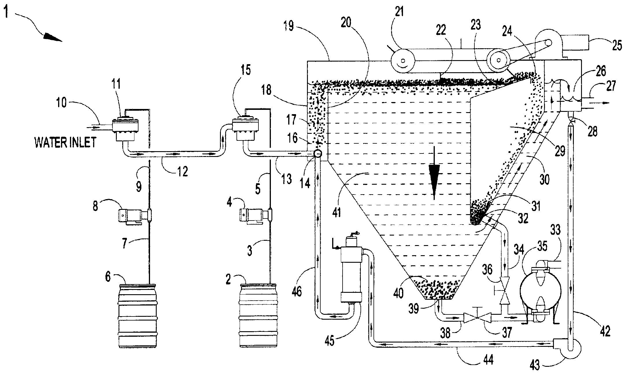
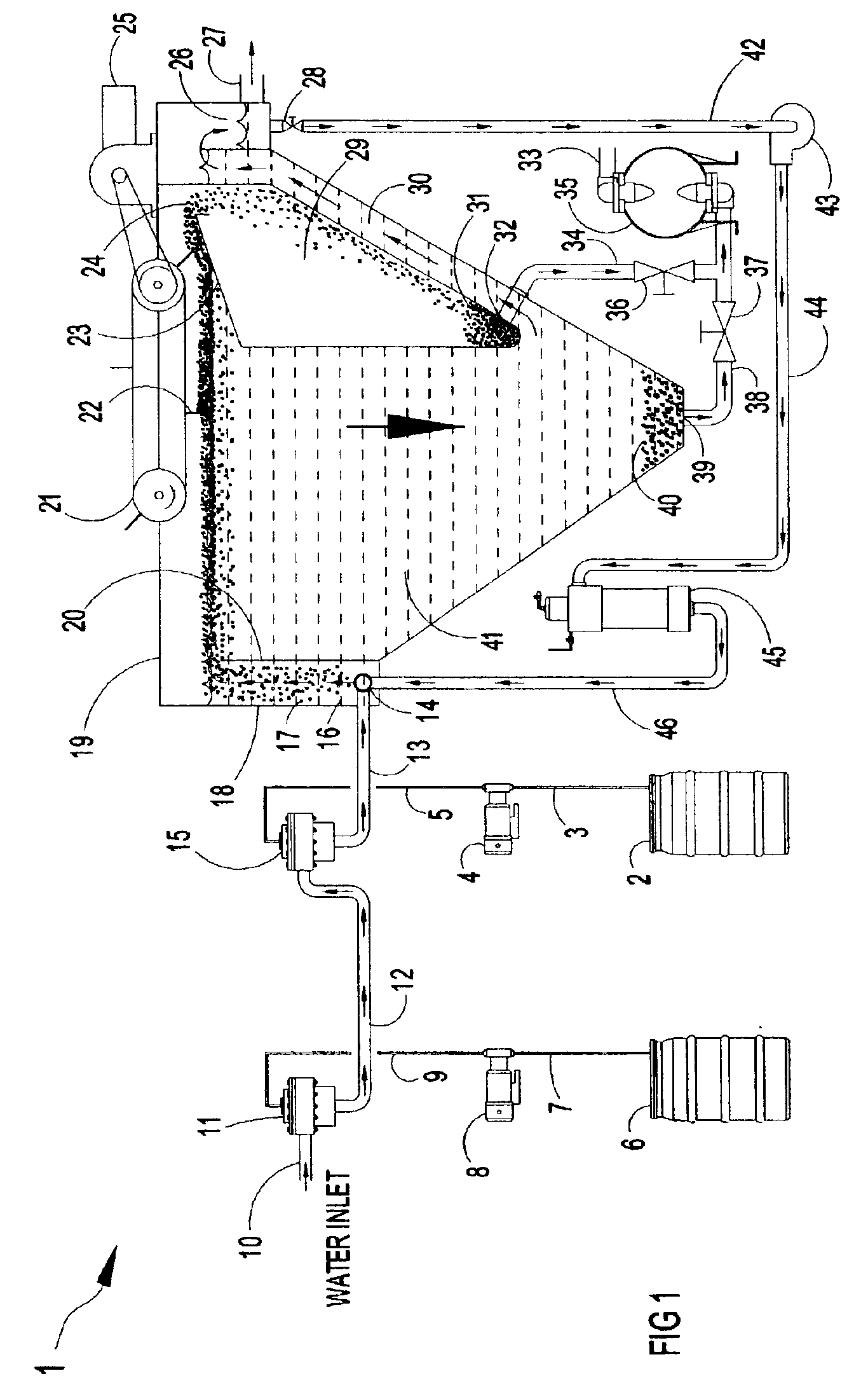
Apparatus for the separation of solids from liquids by dissolved gas floatation

Inactive Publication Date: 2005-11-01
HYDROTREAT
View PDF36 Cites 47 Cited by
  • Summary
  • Abstract
  • Description
  • Claims
  • Application Information

AI Technical Summary

Benefits of technology

"The present invention provides a new method and apparatus for mixing solid chemicals and dissolving the gas used to create microscopic bubbles for separation of suspended solids and organic contaminants from water by dissolved gas floatation. The apparatus includes a dissolved gas floatation clarifier, liquid-gas mixers, liquid-liquid mixers, solid-liquid chemical feeders, settling zones, sludge pumps, recycle pressure aeration systems, and chemical feed systems. The technical effects of the invention include improved separation efficiency, reduced sludge production, and reduced chemical consumption."

Problems solved by technology

Most of the deficiencies of the present dissolved gas floatation systems are in the quality of the bubbles produced, size and cost of the apparatus used to generate the bubbles, method of introducing the bubbles into the stream of water to be treated, and the success of mixing and dispersing the chemicals added by the existing apparatus used.

Method used


Image

  • Apparatus for the separation of solids from liquids by dissolved gas floatation
  • Apparatus for the separation of solids from liquids by dissolved gas floatation
  • Apparatus for the separation of solids from liquids by dissolved gas floatation

Examples


second embodiment

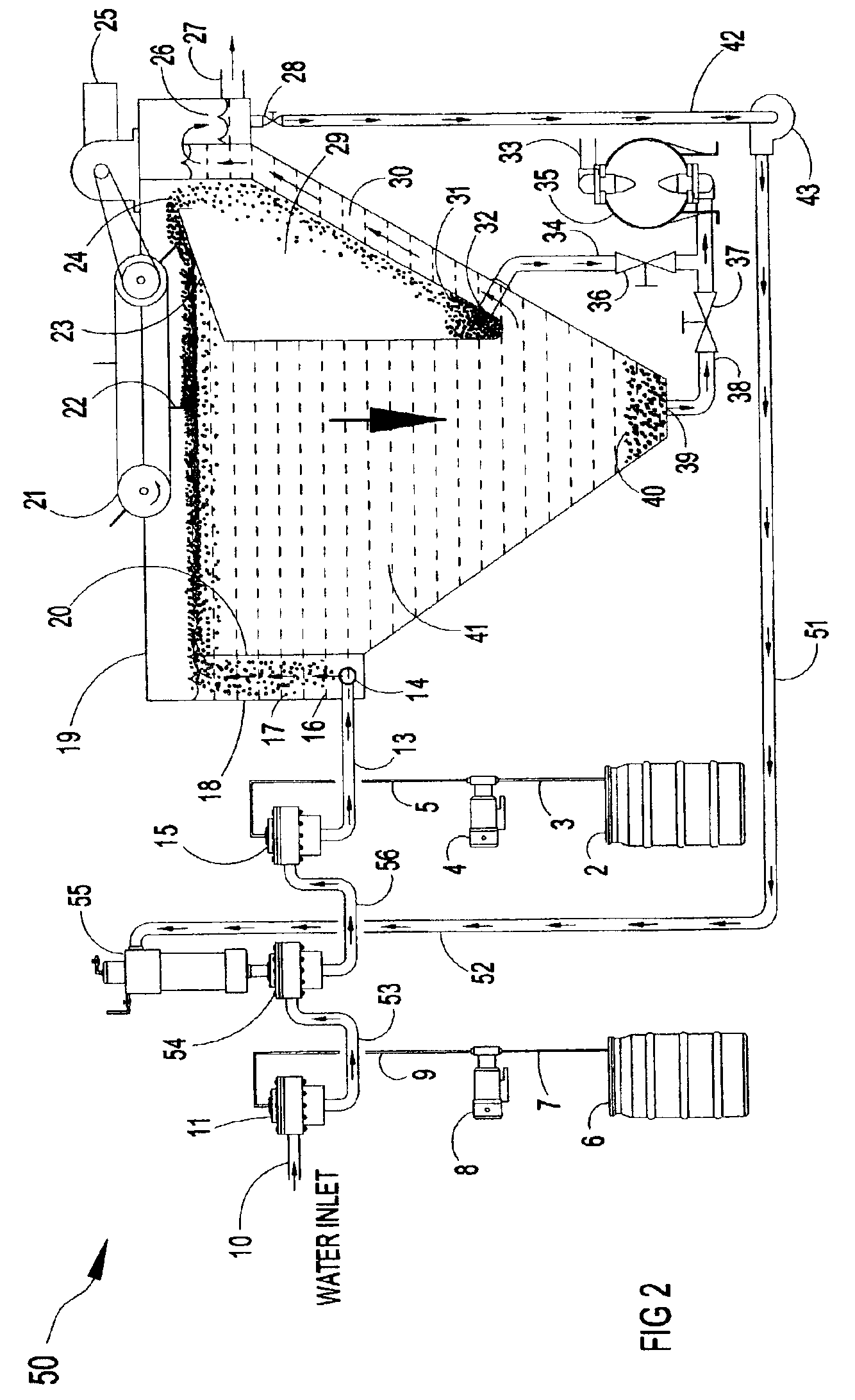
[0037]FIG. 2 depicts in schematic representation a dissolved gas flotation clarifier system 50 employing another recycle pressure aeration system for separating suspended solids and trace organic fluids in accordance with the present invention. The dissolved gas floatation clarifier system 50 consists of a water inlet 10 for the contaminated wastewater to be clarified, an inline fluid mixer 11 for introduction of coagulation agents with a chemical feed pump 8 and chemical supply container 6, a second inline fluid mixer 54 for introduction of dissolved air from the recycled pressure aeration system for flotation, a third inline fluid mixer 15 for introduction of flocculating agents with a chemical feed pump 4 and chemical supply 2, a dissolved gas floatation (DGF) clarifier 19, and a recycle pressure aeration system with a recycling pump 43 and a fluid mixer applied as a dissolved gas generator 55 connected to the second inline fluid mixer 54.

[0038]The dissolved gas clarifier 19 cons...

third embodiment

[0045]FIG. 3 depicts in schematic representation a dissolved air clarifier system 60 employing a full stream pressure aeration system for separating suspended solids and trace organic fluids in accordance with the present invention. The dissolved gas floatation clarifier system 60 consists of a water inlet 10 for the contaminated wastewater to be clarified, an inline fluid mixer 11 for introduction of coagulation agents with a chemical feed pump 8 and chemical supply container 6, a second inline fluid mixer applied as a dissolved gas generator 62 for introduction of dissolved air in the full incoming wastewater stream for flotation, a third inline fluid mixer 15 for introduction of flocculating agents with a chemical feed pump 4 and chemical supply 2, and a dissolved gas floatation (DGF) clarifier 19.

[0046]The dissolved gas clarifier 19 consist an inlet manifold 14, a retention chamber 18 where the microscopic bubbles form and become attached to the contaminants, a floatation cell 4...


PUM

PropertyMeasurementUnit
outer diameteraaaaaaaaaa
diameteraaaaaaaaaa
wettingaaaaaaaaaa

Abstract

The present invention relates to methods and apparatus for separation of solids from liquids and separation of liquids from liquids (such as oil from water) by dissolved gas floatation. A dissolved gas floatation clarifier is described as is a liquid-gas mixer, a liquid-liquid mixer, and solid-liquid chemical feeders. The methods and apparatus of the present invention are particularly suitable for supplying dissolved air and mixing of chemicals for use in separation of solids in dissolved air floatation clarifiers.

Description

CROSS REFERENCE TO RELATED APPLICATIONS[0001]This application is a continuation-in-part of patent application Ser. No. 09 / 879,496, filed Jun. 12, 2001, entitled “Method and Apparatus for Mixing Fluids, Separating Fluids, and Separating Solids from Fluids,” by Johnny Arnaud, which is hereby incorporated by reference in its entirety, now U.S. Pat. No. 6,669,843.BACKGROUND OF THE INVENTION[0002]1. Field of the Invention[0003]The present invention relates to methods and apparatus for separation of solids from liquids and separation of liquids from liquids (such as oil from water) by dissolved gas floatation. The methods and apparatus of the present invention are particularly suitable for supplying dissolved air and mixing of chemicals for use in separation of solids in dissolved air floatation clarifiers.[0004]2. Description of Related Art[0005]The methods and apparatus for mixing fluids and dissolving gases in liquids disclosed in co-pending patent application Ser. No. 09 / 879,496, file...

Claims


Application Information

Patent Timeline
Patent Type & Authority Patents(United States)
IPC IPC(8): B01D21/24B03D1/14E21B43/34E21B43/12E21B43/16B01D17/035B01D17/038B01D17/12B01D65/00
CPCB01D21/2433B01D21/245E21B43/122E21B43/128E21B43/129E21B43/166E21B43/34B03D1/1475B03D1/1431B03D1/1462B01D21/0084B01D17/0214B01D17/00B01D21/26
Inventor ARNAUD, JOHNNY
Owner HYDROTREAT
Learn More