Apparatus for hydrocracking and/or hydrogenating fossil fuels

a technology of fossil fuels and hydrocracking, which is applied in the direction of lighting and heating apparatus, separation processes, furnaces, etc., can solve the problems of affecting the production efficiency of the apparatus, the f-t process is particularly fragile, and the commercially uncompetitive for crude oil discovery and production, etc., and achieves efficient separation

Inactive Publication Date: 2005-11-01
HEADWATERS TECH INNOVATION LLC +1
View PDF5 Cites 51 Cited by
  • Summary
  • Abstract
  • Description
  • Claims
  • Application Information

AI Technical Summary

Benefits of technology

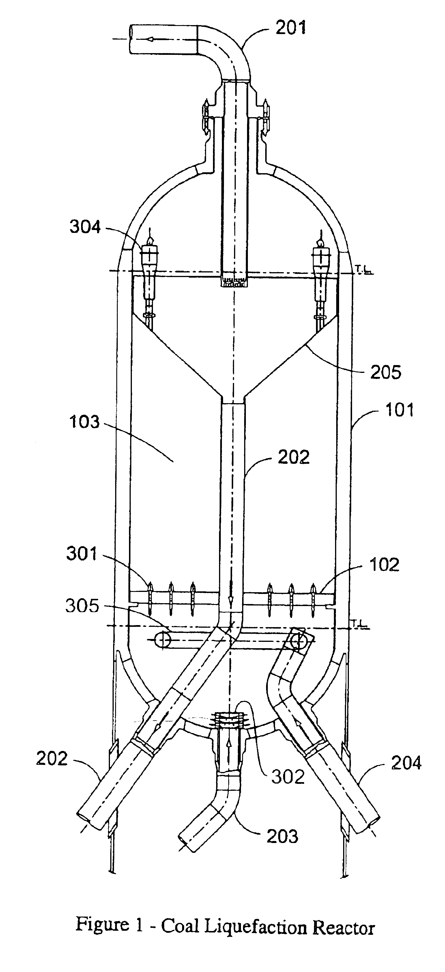
[0015]The configuration of the reactor circulating pump distribution means serves to create a whirlpool effect in the bottom head of the reactor as recycle liquid is pumped though the distribution means. The whirlpool effect itself causes coal particles that may be deposited on the bottom of the reactor to become re-suspended in the feed stream and so avoid solid settling and coking. Also, a better mixing of liquid and hydrogen from the feed is achieved.
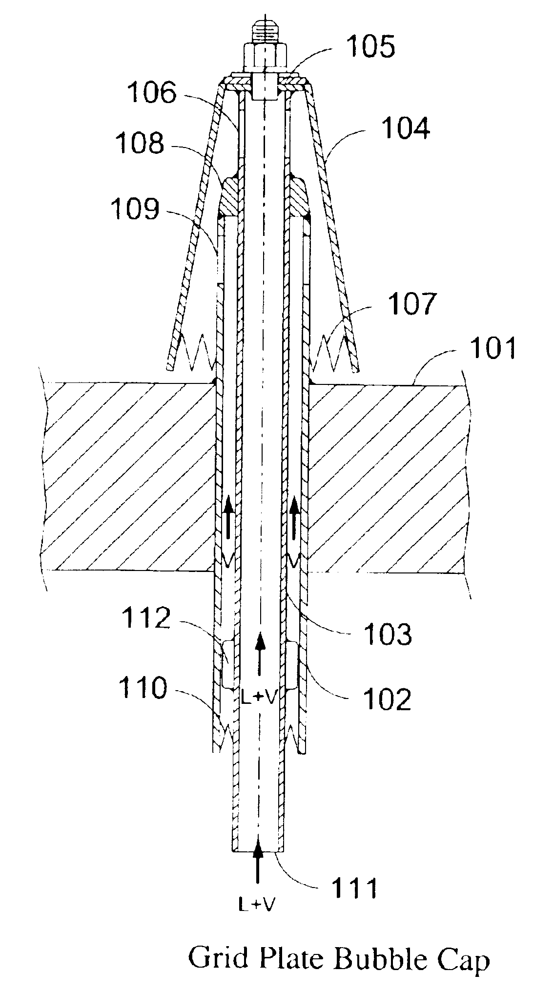
[0017]The tapered bubble cap of the invention with the serrated edges produces much smaller bubbles over prior art bubble caps and, therefore, a greater total hydrogen bubble surface area which provides an accelerated mass transfer. The tapered bubble cap also results in less pressure drop as there is no need to change the direction of the flow of the exiting gas as experienced by non-tapered bubble caps. The double pipe shell-in-shell also eliminates the vibration or pulsation problems experienced in the prior art reactors containing single pipe bubble caps.
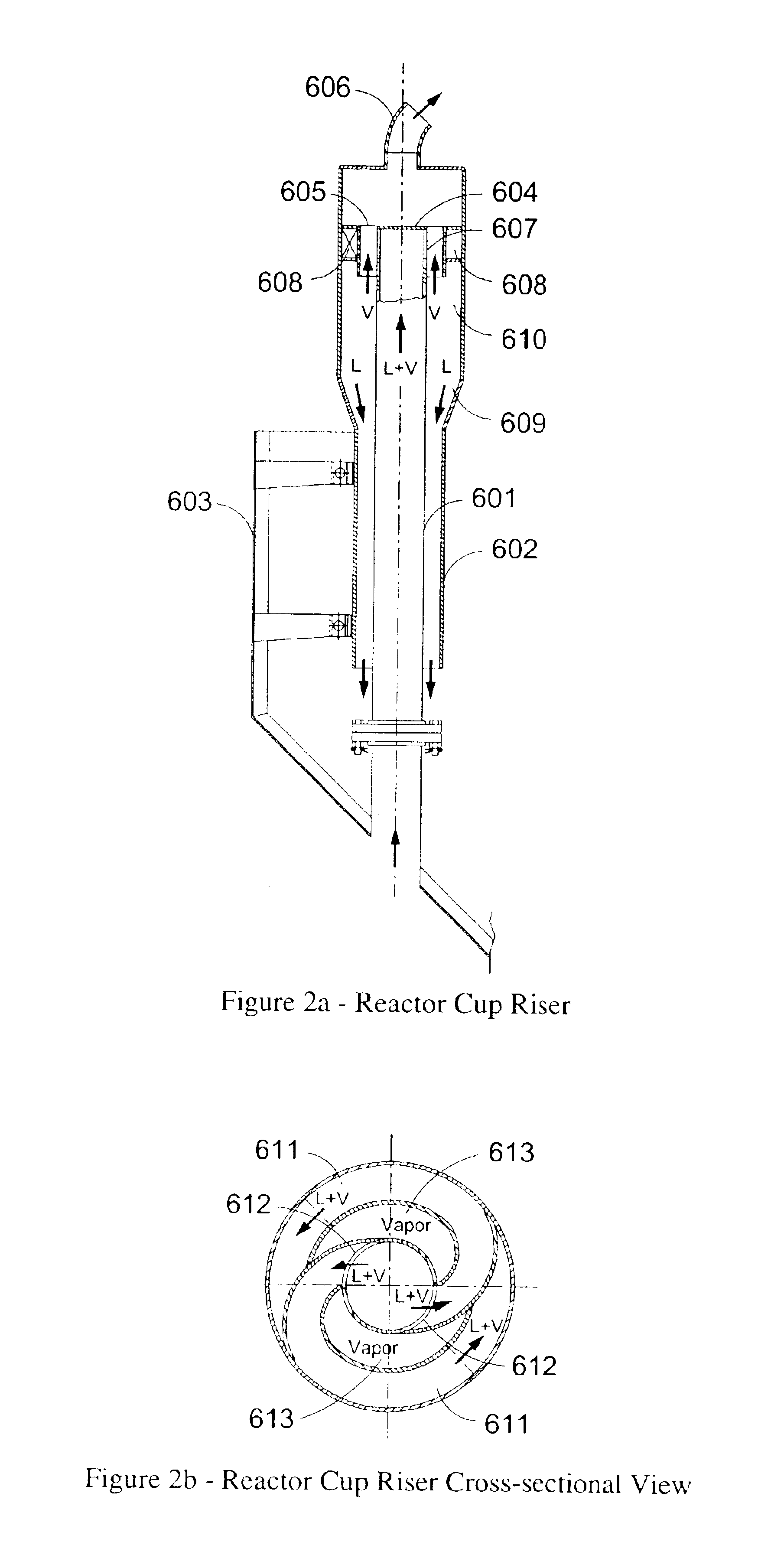
[0020]The cup riser of the invention provides a very efficient separation of the liquid and vapor and / or solids output from the catalytic slurry bed. Consequently, the pump for the liquid recycle stream experiences little or no cavitation, eliminating pump failure as a cause for process shut-downs.

Problems solved by technology

Both the German and SASOL projects were driven by political necessity but were otherwise commercially uncompetitive with crude oil discovery and production.
However, precipitated iron catalysts in the F-T process are especially fragile and break down easily under conventional reaction conditions into very fine particles which are carried over into the hydrocarbon liquid products.

Method used


Image

  • Apparatus for hydrocracking and/or hydrogenating fossil fuels
  • Apparatus for hydrocracking and/or hydrogenating fossil fuels
  • Apparatus for hydrocracking and/or hydrogenating fossil fuels

Examples


Embodiment Construction

[0027]The inventions described herein are preferably intended to be utilized in advancing the art of high pressure catalytic slurry bed reactor vessels employed in the conversion of fossil fuels, particularly coal, heavy petroleum oils and tar sands into light hydrocarbons useful as fuels and chemicals. These vessels also include the known reactors used in the H-Oil process, the LCFining process, the H-Coal process, as well as others. As noted herein before, the use of ebullating bed catalysis reactor technology is well known to those skilled in the art and the advantages and disadvantages of the reactor technology is well documented in the art. The inventions presented herein are intended to advance those advantages and overcome those disadvantages. However, it will also be apparent to those skilled in the art that the inventions described herein can have useful applications in chemical apparatuses outside the scope of just ebullating bed reactor vessels and may be useful, individu...


PUM

PropertyMeasurementUnit
temperatureaaaaaaaaaa
partial pressureaaaaaaaaaa

Abstract

A catalytic hydrocracking reactor vessel for the conversion of a hydrogen gas and fossil fuel feedstream to light liquid hydrocarbons. The reactor vessel comprises reactor cup riser with a helical cyclonic separator conduit for separating a liquid and vapor product stream to provide an essentially vapor-free liquid recycle stream, a grid plate bubble cap with a tapered bell cap wall housing having serrated edges for producing small hydrogen bubbles of increased total surface area of bubbles at lower pressure drop, optionally a feedstream inlet pipe sparger containing rows of downward directed slots for even distribution of the feedstream across the cross-sectional area of the reactor and providing free drain of solid particles from the sparger, and optionally a liquid recycle inlet distributor containing vertically curved plates for creating a whirling motion in the liquid recycle stream for better mixing with the feedstream with minimal solids settling.

Description

FIELD OF THE INVENTION[0001]This invention relates to an apparatus for converting coal, petroleum residue, tar sands and similar materials to hydrocarbon liquids or gases. The invention particularly relates to an advantageous reactor design that overcomes several reactor-associated performance problems and improves the overall efficacy of the conversion steps occurring in the reactor, particularly the catalytic hydrogenation and / or hydrocrackng of coal particles into hydrocarbon liquids in catalytic slurry reactors.BACKGROUND OF THE INVENTION[0002]The conversion of fossil fuels such as coal, natural gas and peat to liquid hydrocarbon fuels and / or chemicals has been the subject of intensive research and development throughout the industrialized world for many years to provide a practical alternative to petroleum crude oil production and open-up the world's vast reserves of coal as a competitive source for essential hydrocarbons. Many processes have been developed for the direct or in...

Claims


Application Information

Patent Timeline
Patent Type & Authority Patents(United States)
IPC IPC(8): B01J8/22B01J8/20C10G1/06C10G1/08C10G47/24C10G49/00
CPCB01J8/22B01J8/224B01J8/226C10G1/065C10G1/083C10G47/24C10G49/002
Inventor KAO, THOMASCHANG, ROBERT
Owner HEADWATERS TECH INNOVATION LLC
Why Eureka
Try Eureka