
Virtual space control data receiving apparatus,virtual space control data transmission and reception system, virtual space control data receiving method, and virtual space control data receiving program storage media

a virtual space control and data receiving technology, applied in the field of virtual space control data receiving apparatus, can solve the problems of inability to set the motion in real time to a complicated shape such as a human, affecting the quality of the video data, and requiring a large amount of time and cost for the transmission of video data, so as to facilitate facilitate the effect of facilitating the conversion of control data to motion data

Inactive Publication Date: 2005-11-01
PANASONIC CORP
View PDF6 Cites 104 Cited by
  • Summary
  • Abstract
  • Description
  • Claims
  • Application Information

AI Technical Summary

Benefits of technology

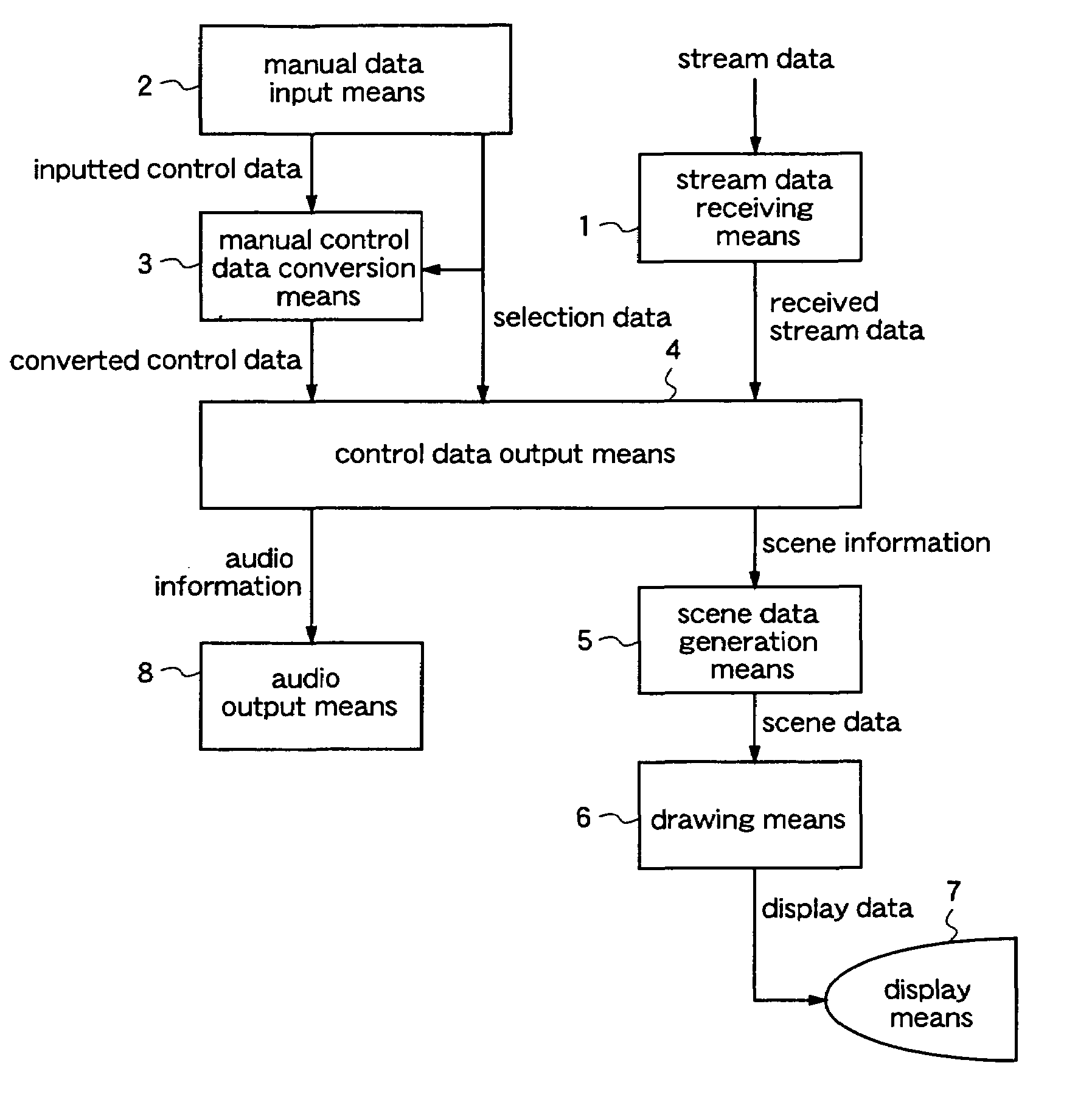
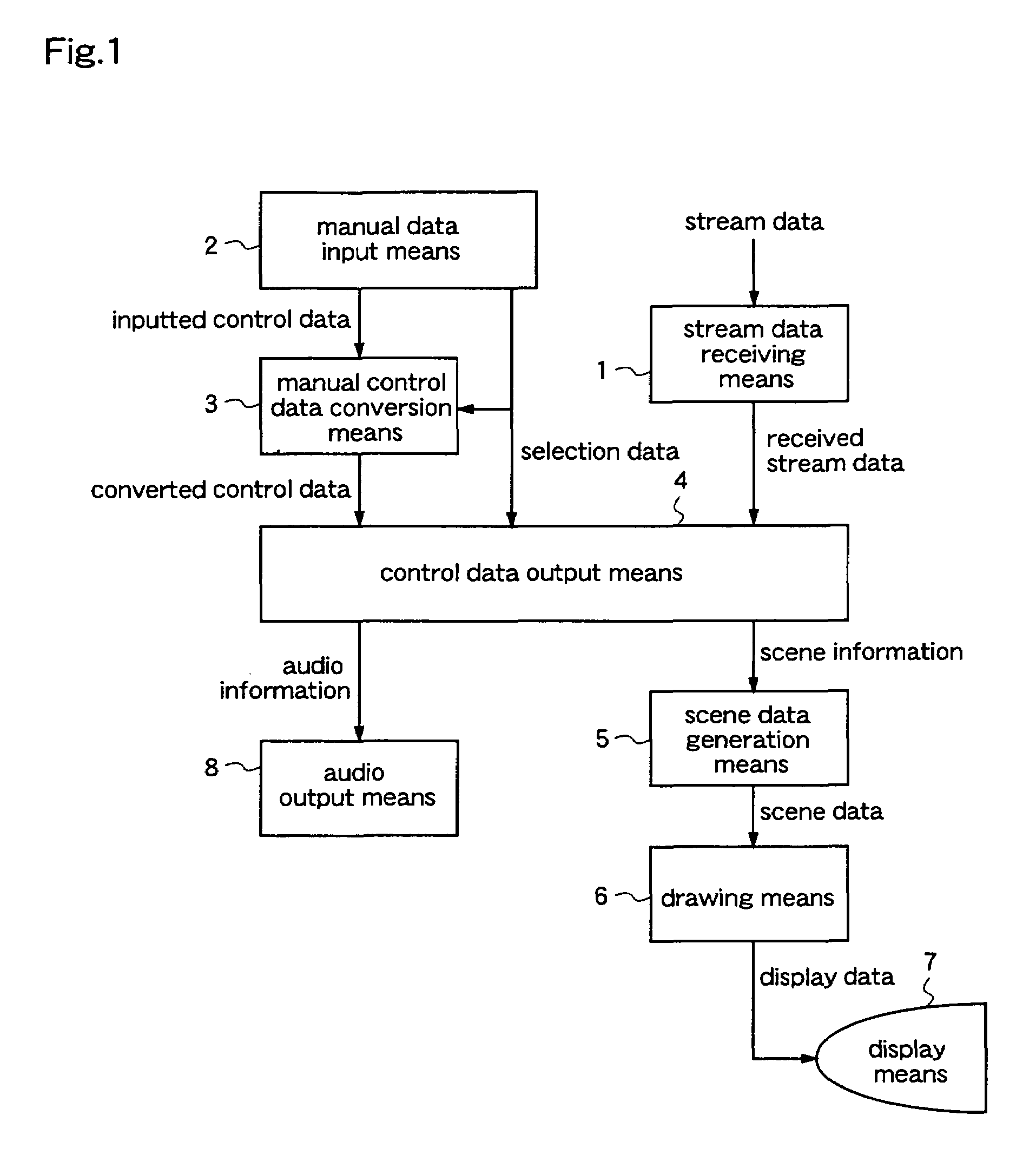
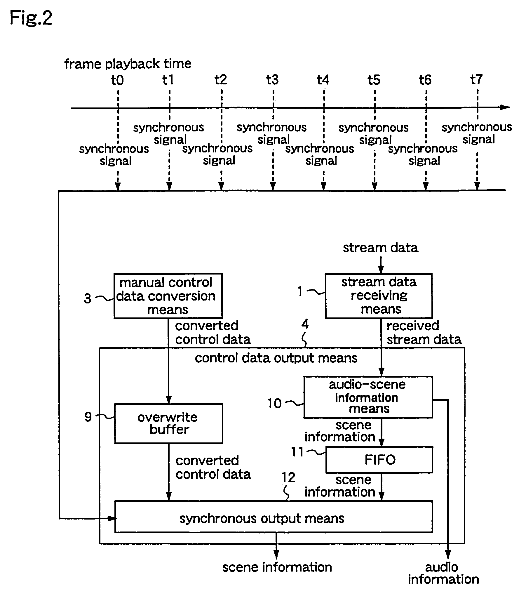
[0013]According to a third aspect of the present invention, the virtual space control data receiving apparatus of the second aspect further comprises: manual control data conversion means for converting the control data input by the manual data input means, into control data suited to the object selected by the manual data input means; and the control data output means for outputting the control data converted by the manual control data conversion means, for the object selected by the manual data input means, and outputting the stream data received by the stream data receiving means, for the other objects. Therefore, in a dynamic virtual space represented by 3-dimensional CG, static image, dynamic image, audio, and text which are based on a network such as the Internet, the viewer can control a plurality of objects to be controlled, by using the same control data.
[0032]According to a twenty-second aspect of the present invention, in the virtual space control data receiving apparatus according to any of the eleventh, twelfth, fifteenth, and sixteenth aspects, physical calculation for expressing physical characteristics of the selected object or part is used when the manual control data conversion means converts the inputted control data to motion data of an object of a part of an object. Therefore, conversion of control data to motion data is facilitated.

Problems solved by technology

In the conventional data format mainly composed of video data and text data, such as HTML (Hyper Text Markup Language), enormous time and cost are required for transmitting video data, especially, animation data.
Therefore, in the existing system, network traffic is restricted.
However, with the conventional 3-dimensional CG modeling languages on the Internet such as the VRML, it is impossible to set the motion in real time to a complicated shape such as a human being.
Further, under the existing circumstances, it is impossible to transmit or receive motion data of a 3-dimensional CG character which moves as real as a human being, in real time, through a narrow band network such as a telephone line.
In this prior art, however, although reproduction of a scene according to the stream data can be performed in real time, a viewer cannot enter the scene interactively to control the generated scene itself.
For example, even when the viewer wants to control an object in a virtual space, although the object moves according to the will of the producer of the virtual space (i.e., it moves according to the stream data), the viewer cannot control the object.
Further, the prior art cannot meet the viewer's demand to change the object to be controlled.

Method used


Image

  • Virtual space control data receiving apparatus,virtual space control data transmission and reception system, virtual space control data receiving method, and virtual space control data receiving program storage media
  • Virtual space control data receiving apparatus,virtual space control data transmission and reception system, virtual space control data receiving method, and virtual space control data receiving program storage media
  • Virtual space control data receiving apparatus,virtual space control data transmission and reception system, virtual space control data receiving method, and virtual space control data receiving program storage media

Examples


embodiment 1

[0058]Hereinafter, a virtual space control data receiving apparatus according to a first embodiment of the present invention will be described with reference to drawings. In this first embodiment, a dynamic virtual space is defined as a virtual space constituted by 3-dimensional CG and audio, and the constituents of the virtual space include dynamic elements (i.e., time-varying elements), for example, elements which move or change in shape with time, mapped textures to be changed with time (including dynamic image mapping), and audio to be changed with time. Further, with respect to 3-dimensional CG, besides the ordinary 3-dimensional CG technique, the 3-dimensional CG animation technique is included.

[0059]FIG. 1 is a block diagram illustrating the structure of the virtual space control data receiving apparatus according to the first embodiment. With reference to FIG. 1, the virtual space control data receiving apparatus comprises a stream data receiving means 1, a manual data input...

embodiment 2

[0075]FIG. 3 is a block diagram illustrating the structure of a virtual space control data receiving apparatus according to a second embodiment of the present invention. The virtual space control data receiving apparatus comprises a stream data transmission means 21, a client unit A 22, a client unit B 23, a data transmission / reception line 24, a stream data receiving means 25, a manual data input means 26, a manual data transmission means 27, a manual data receiving means 28, a manual control data conversion means 29, a control data output means 30, a scene data generation means 31, a drawing means 32, a display means 33, and an audio output means 34.

[0076]The client unit B 23 has the same structure as that of the client unit A 22. While in this second embodiment the processes will be described with two client units, the contents of the processes are identical even when three or more client units are provided. Therefore, a virtual space control data receiving apparatus having three...

embodiment 3

[0087]FIG. 4 is a block diagram illustrating the structure of a virtual space control data transmission and reception system according to a third embodiment of the present invention. This system comprises a stream data transmission means 51, a client unit A 52, a client unit B 53, a manual control data transmission means 54, a data transmission / reception line 55, a stream data receiving means 56, a manual data input means 57, a manual data transmission means 58, a manual data receiving means 59, a manual control data conversion means 60, a control data output means 61, a scene data generation means 62, a drawing means 63, a display means 64, and an audio output means 65. The structure of the client unit B 53 is identical to that of the client unit A 52. While in this third embodiment two client units are used to explain the processes performed by the virtual space control data transmission and reception system, the contents of the processes are identical even when three or more clie...


PUM


Abstract

A virtual space control data receiving apparatus comprises stream data receiving means for receiving a plurality of stream data for controlling a dynamic virtual space, according to the type of each stream data; manual data input means for inputting control data for an object to be controlled in the virtual space; and control data output means for outputting the control data input by the manual data input means, for the object controlled by the manual data input means, and outputting the stream data received by the stream data receiving means, for the other objects. Therefore, in a dynamic virtual space represented by 3-dimensional CG, static image, dynamic image, audio, and text which are based on a network such as the Internet, the virtual space can be reproduced in real time, and the viewer can selectively control an object.

Description

FIELD OF THE INVENTION[0001]The present invention relates to a virtual space control data receiving apparatus, a virtual space control data transmission and reception system, a virtual space control data receiving method, and a virtual space control data receiving program storage medium and, more particularly, to those for controlling a dynamic virtual space represented by three-dimensional computer graphics (hereinafter referred to as 3-dimensional CG), static image, dynamic image, audio, and text which are based on a network such as the Internet.BACKGROUND OF THE INVENTION[0002]In recent years, virtual malls, electronic commerce, and related home pages, such as WWW (World Wide Web) on the Internet, have attracted attention as utilization fields of 3-dimensional CG. Especially, the rapid progress of the Internet provides an environment in which relatively high definition 3-dimensional CG such as games and movies are easily handled at home. In the conventional WWW, a machine called ...

Claims


Application Information

Patent Timeline
IPC IPC(8): A63F13/12G06F3/00G06T17/40H04L29/08H04L29/06G06F3/01G06T13/20G06T19/20H04N21/44H04N21/61H04N21/6547
CPCA63F13/12G06F3/011H04L29/06027H04N21/44012H04N21/6125H04N21/6547G06T13/20G06T19/20A63F2300/50A63F2300/6607G06T2219/2016G06T2219/2021A63F13/30A63F13/63A63F13/52A63F13/35H04L65/1101
Inventor MOCHIZUKI, YOSHIYUKINAKA, TOSHIYAASAHARA, SHIGEO
Owner PANASONIC CORP
Learn More