Leg joint assist device for leg type movable robot

a technology of assist device and leg joint, which is applied in the direction of shock absorbers, program control, instruments, etc., can solve the problems of large size and weight of electric motors, large impact force, and large impact force, so as to reduce the burden on the joint actuator of the specific joint, prevent free vibration of spring means, and minimize the effect of energy loss from joule heat or the lik

Inactive Publication Date: 2005-11-08
HONDA MOTOR CO LTD
View PDF8 Cites 63 Cited by
  • Summary
  • Abstract
  • Description
  • Claims
  • Application Information

AI Technical Summary

Benefits of technology

[0018]Moreover, in the present invention, the spring means may be a solid spring such as a coiled spring, a leaf spring, a torsion spring, a metal spring, rubber and the like, as a matter of course. However, it is preferred that the spring means be a gas spring which elastically generates the auxiliary driving force by compression and expansion of gas. Specifically, the gas spring unlikely to cause free vibration in comparison with the solid spring. Therefore, free vibration of the spring means can be prevented especially when transmission of the relative displacement motion to the spring motion is discontinued. Thus, when the transmission of the relative displacement motion to the spring means is re-started after transmission thereof has been discontinued, the desired auxiliary driving force of the spring means can be generated smoothly.
[0019]Moreover, in the pr

Problems solved by technology

Consequently, driving forces (torque), which should be generated to the joint actuators to resist the forces, are likely to be relatively large.
With any of these operations, however, it is required to energize the electric motor or a power source such as a battery with a high current.
Thus, an energy loss by Joule heat or the like is likely to be lar

Method used


Image

  • Leg joint assist device for leg type movable robot
  • Leg joint assist device for leg type movable robot
  • Leg joint assist device for leg type movable robot

Examples


first embodiment

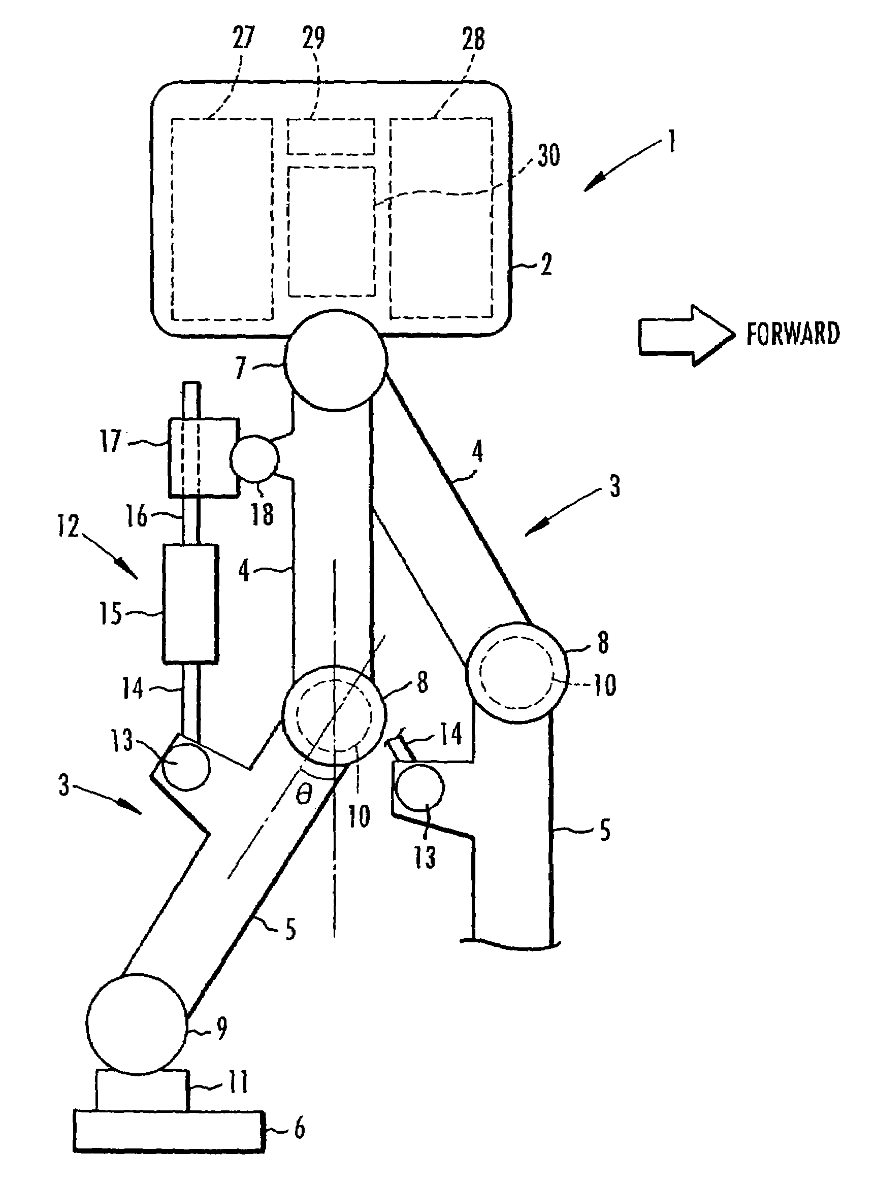
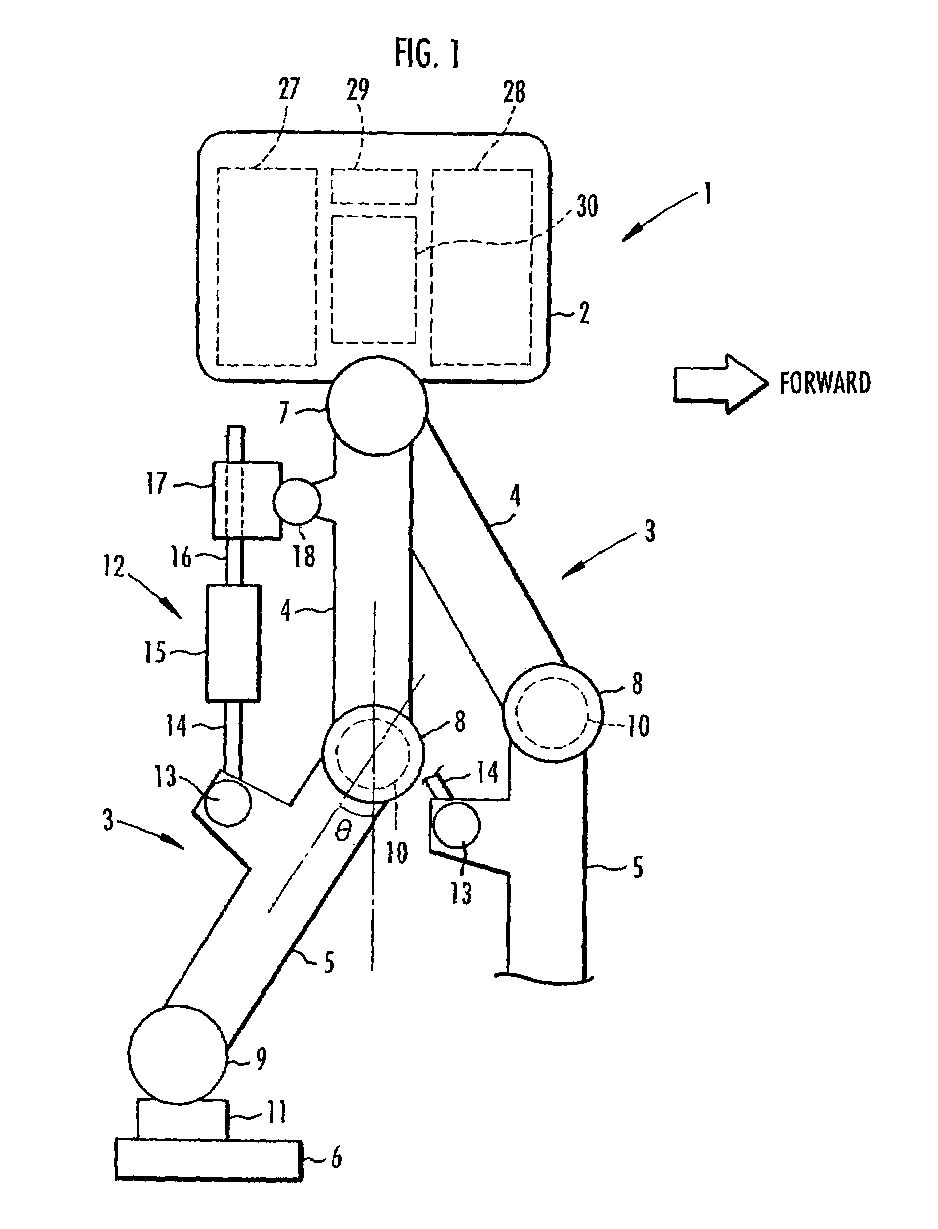
[0047]the present invention is described with reference to FIGS. 1 to 8. FIG. 1 is a schematic view depicting a configuration of a biped mobile robot as the legged mobile robot of this embodiment. As illustrated, the robot 1 is provided with two legs 3 and 3 extending downward from a body 2. Note that these legs 3 and 3 have the same structure and thus one of the legs 3 (the forward-left leg 3 of the robot 1 in the figure) is shown only partially.

[0048]Similarly to the leg of a human, each of the legs 3 is configured by sequentially connecting a thigh portion 4, a crus portion 5, and a foot portion 6 through a hip joint 7, a knee joint 8, and an ankle joint 9, respectively, from the body 2. To be more specific, the thigh portion 4 of each of the legs 3 extends from the body 2 through the hip joint 7, the crus portion 5 is connected to the thigh portion 4 through the knee joint 8, and the foot portion 6 is connected to the crus portion 5 through the ankle joint 9. Note that respectiv...

third embodiment

[0108]Further, as shown in FIG. 12(b), the locked state of the lock mechanism 39 is a state where the latch pin 25 is moved forward and fitted into one of the recesses 16a′ of the rod member 16. In this locked state, the actuation of the assist device 12 is similar to that of the foregoing Specifically, when the knee bending angle becomes larger than the knee bending angle at the start time of the locked state (lock start knee bending angle), the spring means 15 stores elastic energy and generates an elastic force. This elastic force then acts on the knee joint 8 in the stretching direction of the leg 3. Moreover, when the knee bending angle becomes smaller than the lock start knee bending angle, the latch pin 25 is withdrawn from the recess 16a′, since each of the recesses 16a′ has the aforementioned tapered surface 16b. Thereafter, the rod member 16 moves as shown by an arrow in FIG. 12(b). Therefore, the spring means 15 is kept in the almost natural length state, and thus the au...

sixth embodiment

[0122]Here, the connecting structure of the pulley 53 and the crus portion 5 is more specifically described with reference to FIG. 17. Similar to the case of the aforementioned sixth embodiment, the rotating shaft portion 49 of the crus portion 5 is rotatably supported by the thigh portion 4 through the bearing 50. One end portion of the rotating shaft portion 49, projecting to the outside of the thigh portion 4, is connected to the output side of the speed reducer 56. The input shaft 56a of the speed reducer 56 is releasably connected to the rotating shaft portion 53a of the pulley 53 through the clutch mechanism 55. In this case, the clutch mechanism 55 fixes the rotating shaft portion 53a of the pulley 53 to the input shaft 56a of the speed reducer 56 and releases the fixed rotating shaft portion 53a. The clutch mechanism 55 is configured by an electromagnetic clutch or the like. During the knee bending and stretching motion, the speed reducer 56 increases the rotation speed of t...


PUM


Abstract

An assist device that applies an auxiliary driving force to a joint in parallel with a driving force of a joint actuator between a thigh portion and a crus portion, which are a pair of link members of a leg. The assist device generates the auxiliary driving force by use of spring device, such as a solid spring or an air spring. A member supporting a rod member connected to the spring device is provided with a device for transmitting a bending and stretching motion of the leg at the joint (a relative displacement motion between the thigh portion and the crus portion) to the spring device to generate an elastic force of the spring device, and for discontinuing the transmission of the bending and stretching motion to the spring device. This transmitting device is controlled in accordance with a gait of a robot. Thus, a burden on the joint actuator is reduced where necessary and favorable utilization efficiency of energy can be stably ensured.

Description

TECHNICAL FIELD[0001]The present invention relates to a leg joint assist device which generates an auxiliary driving force to a joint of a leg of a legged mobile robot such as a biped mobile robot, to assist a joint actuator which is for driving the joint.BACKGROUND ART[0002]In a legged mobile robot with a plurality of legs, each of the legs is configured by sequentially connecting a plurality of link members through a plurality of joints from a body. For example, in a biped mobile robot with two legs like a human, each of the legs is configured by sequentially connecting the link members, which correspond to a thigh portion, a crus portion, and a foot portion, through a hip joint, a knee joint, and an ankle joint, respectively, from a body of the robot. In addition, in the legged mobile robot of this kind, a motion of each of the legs for moving the robot is produced by applying a driving force (torque) to each of the joints of each of the legs by using a joint actuator such as an ...

Claims


Application Information

Patent Timeline
IPC IPC(8): B25J19/00F16F9/00F16F9/06A63H11/18B25J5/00
CPCB25J19/0008F16F9/06B25J19/0091Y10T74/20305
Inventor TAKENAKA, TORUGOMI, HIROSHIHAMAYA, KAZUSHITAKEMURA, YOSHINARIMATSUMOTO, TAKASHIYOSHIIKE, TAKAHIDENISHIMURA, YOICHIAKIMOTO, KAZUSHI
Owner HONDA MOTOR CO LTD
Why Eureka
Try Eureka