
High efficiency external counterpulsation apparatus and method for controlling same

a counterpulsation apparatus and high-efficiency technology, applied in the field of external counterpulsation apparatus and method for controlling the same, can solve the problems of restricting coronary blood flow and limited heart energy supply, and achieve the effect of improving efficiency and utility

Inactive Publication Date: 2005-11-08
VASOMEDICAL
View PDF79 Cites 42 Cited by
  • Summary
  • Abstract
  • Description
  • Claims
  • Application Information

AI Technical Summary

Benefits of technology

"The present invention is about an improved external counterpulsation apparatus and method for controlling it. The apparatus uses inflatable devices to assist in improving circulation in patients with coronary artery disease. The invention aims to improve efficiency and utility of the apparatus. The technical effects of the invention include improved energy demand and supply ratio, increased cardiac output, and reduced cardiac workload. The invention also takes into account the variations in blood flow dynamics and physiological parameters of the human body during diastole. The apparatus includes a plurality of inflatable devices, a source of compressed fluid, and a fluid distribution assembly. The apparatus is controlled to sequentially inflate and deflate each inflatable device using a selectively operable inflation / deflation valve. The invention is useful for improving the effectiveness of external counterpulsation therapy for patients with coronary artery disease."

Problems solved by technology

However, during systole the impedance to coronary flow also increases significantly due to the contracting force of the myocardium, thereby restricting coronary blood flow.
For example, in the case of patients with coronary artery disease, energy supply to the heart is limited.

Method used


Image

  • High efficiency external counterpulsation apparatus and method for controlling same
  • High efficiency external counterpulsation apparatus and method for controlling same
  • High efficiency external counterpulsation apparatus and method for controlling same

Examples


Embodiment Construction

[0034]A detailed description of varied and merely exemplary embodiments of the present invention follows with reference to the accompanying drawings. One skilled in the art will readily recognize that the principles of the invention are equally applicable to other embodiments and applications.

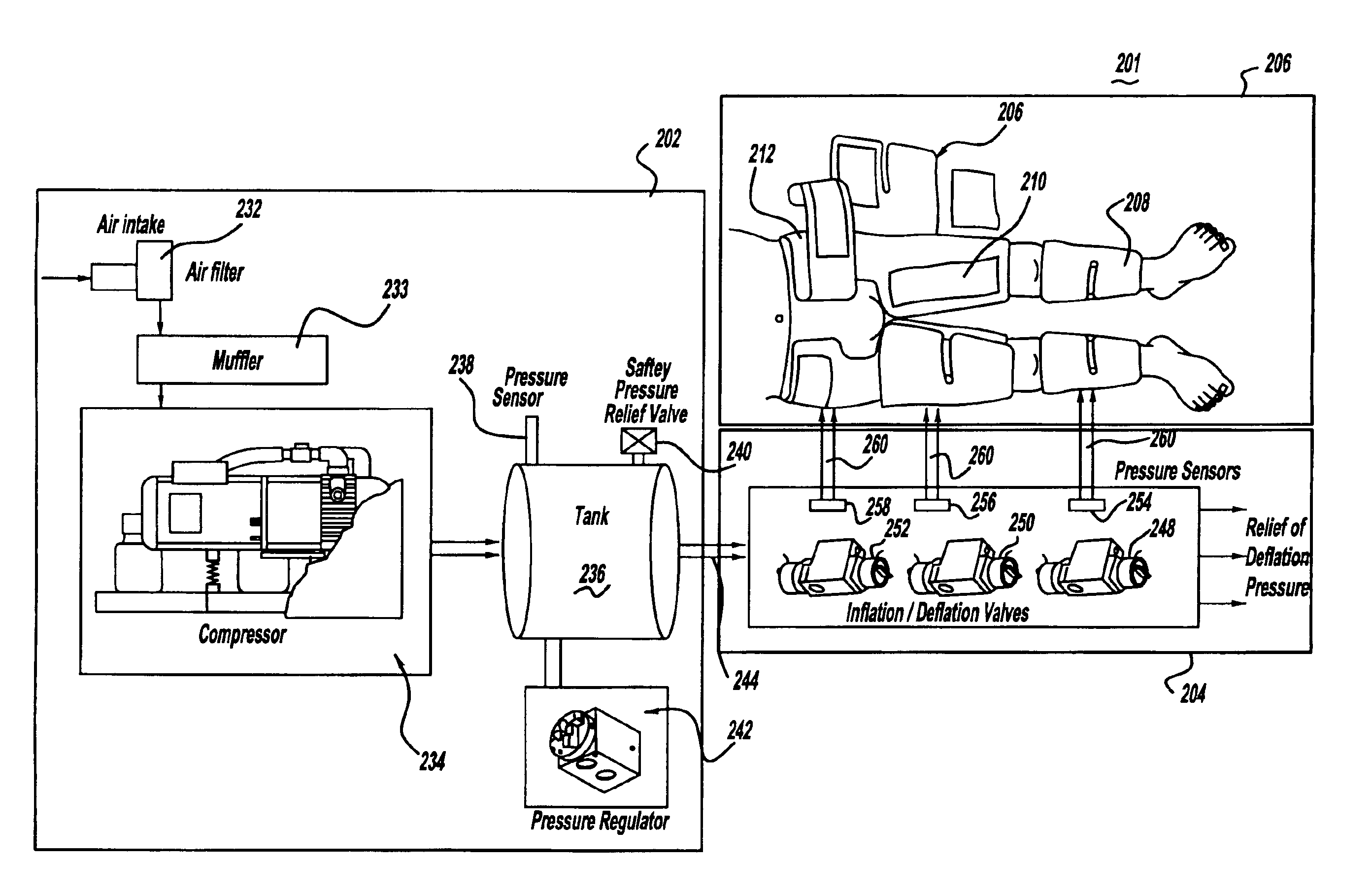
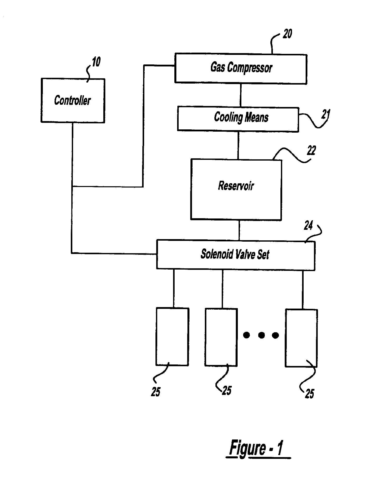
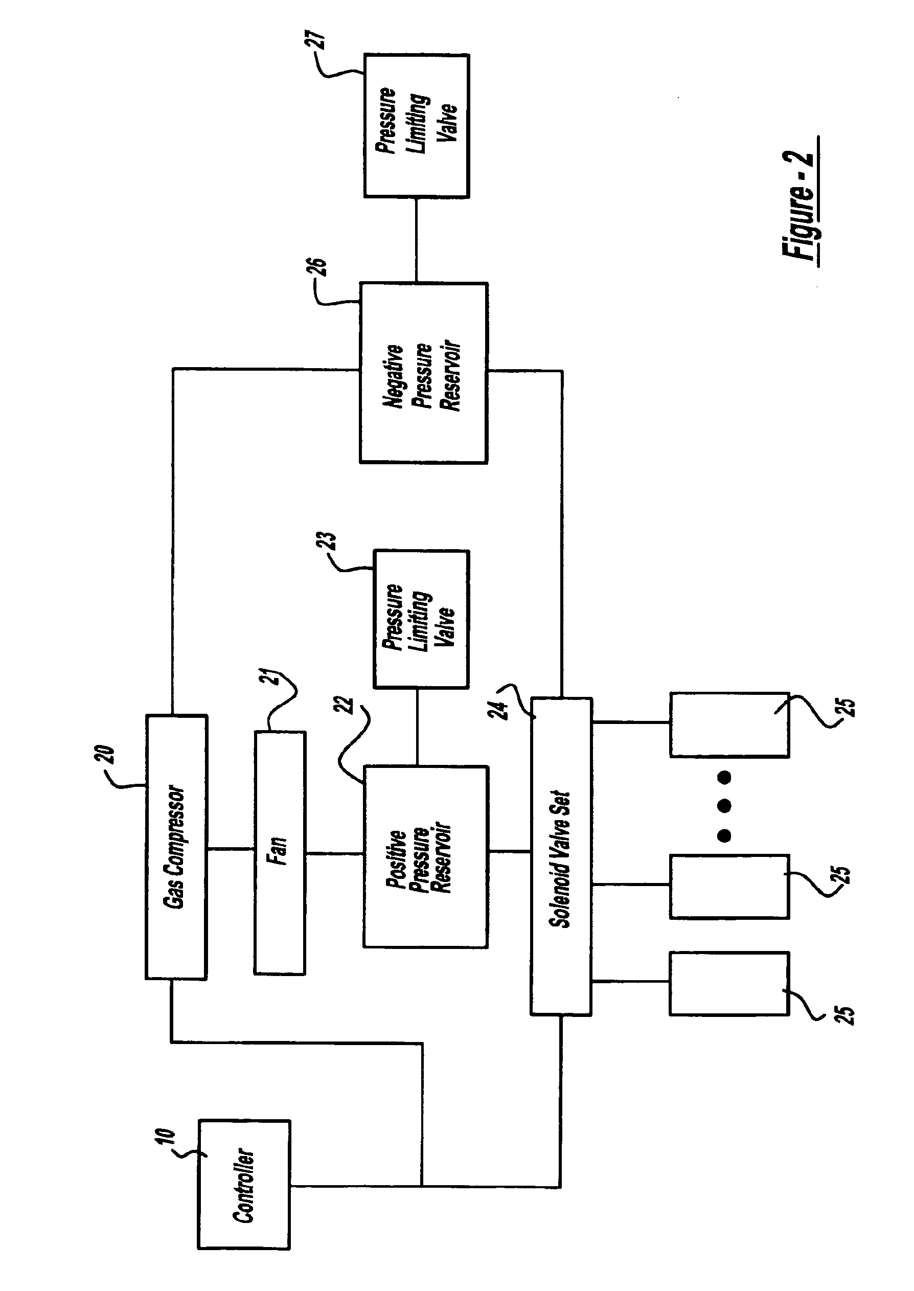
[0035]FIG. 1 is a block diagram of a first exemplary embodiment of an external counterpulsation apparatus according to the present invention, wherein a controller 10 controls the gas compressor 20 and set of solenoid valves 24. The compressor can be of rotary vane, piston, diaphragm or blower type. One suitable compressor is a scroll-type compressor as described in U.S. Pat. No. 5,554,103, commonly assigned and incorporated herein by reference, which essentially consists of two scroll basin with very narrow gaps between them; with one scroll basin adapted to rotate at very high speed (3,000 rpm) while the other scroll basin remains stationary. The clenching of the scroll basins compresses the a...


PUM


Abstract

The present invention provides a high efficiency external counterpulsation apparatus having accurate and reliable timing of inflation and deflation and reduced temperature of the pressurized gas, such that the gas flow temperature of the inflatable devices is near to room temperature, as well as faster and more responsive inflation / deflation equipment. The external counterpulsation apparatus includes a plurality of inflatable devices received about the lower extremities of the patient, a source of compressed fluid in communication with said plurality of inflatable devices, and a fluid distribution assembly interconnecting said source of compressed fluid and said inflatable devices. The fluid distribution assembly includes a selectively operable inflation / deflation valve interconnected between each of said inflatable devices and said source of compressed fluid. The fluid distribution assembly separately operates each inflation / deflation valve to sequentially inflate and deflate each inflatable devices.

Description

[0001]This is a continuation-in-part of application Ser. No. 09 / 710,692, filed Nov. 10, 2000 now U.S. Pat. No. 6,589,267.DISCUSSION OF THE INVENTION[0002]The present invention relates to an external counterpulsation apparatus and method for controlling the same and, more particularly, to such an external counterpulsation apparatus and method for controlling the same having improved efficiency and utility.[0003]External counterpulsation is a noninvasive, atraumatic means for assisting and increasing circulation in patients. External counterpulsation uses the patient's physiological signals related to their heart cycle (e.g., electrocardiograph (ECG), blood pressure, blood flow) to modulate the inflation and deflation timing of sets of compressive cuffs wrapped around a patient's calves, lower thighs and / or upper thighs, including the lower buttocks. The cuffs inflate to create a retrograde arterial pressure wave and, at the same time, push venous blood return from the extremities to ...

Claims


Application Information

Patent Timeline
Patent Type & Authority Patents(United States)
IPC IPC(8): A61G7/057A61H23/04A61H31/00A61G13/06A61G13/00A61G13/08A61H7/00
CPCA61G7/05776A61H9/0078A61H31/00A61H31/005A61H31/006A61H31/008A61G13/06A61G13/08A61H2031/025A61H2201/0103A61H2201/1238A61H2201/165A61H2201/5007A61H2201/501A61H2205/10A61H2230/04A61G2203/46A61H23/04
Inventor HUI, JOHN C. K.
Owner VASOMEDICAL
Learn More