Determination of layer thickness or non-uniformity of layer thickness based on fluorophore additives
a fluorophore additive and layer thickness technology, applied in the direction of fluorescence/phosphorescence, electric/magnetic/electromagnetic heating, instruments, etc., can solve the problems of reducing the performance of the resultant container, reducing the thickness of the polymer layer on line, and degrading the barrier properties
- Summary
- Abstract
- Description
- Claims
- Application Information
AI Technical Summary
Benefits of technology
Problems solved by technology
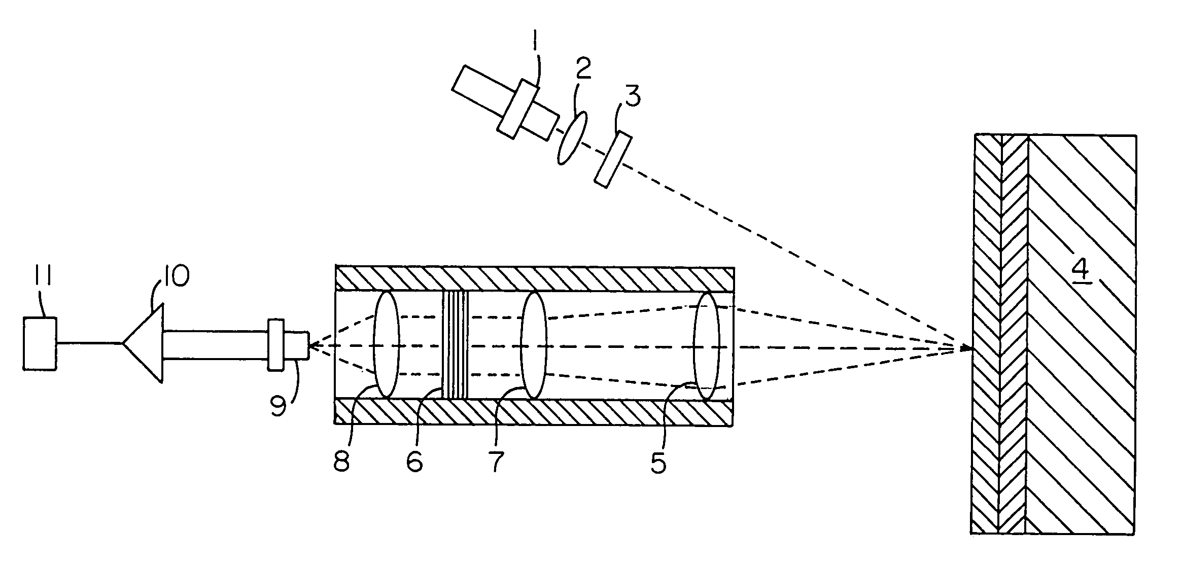
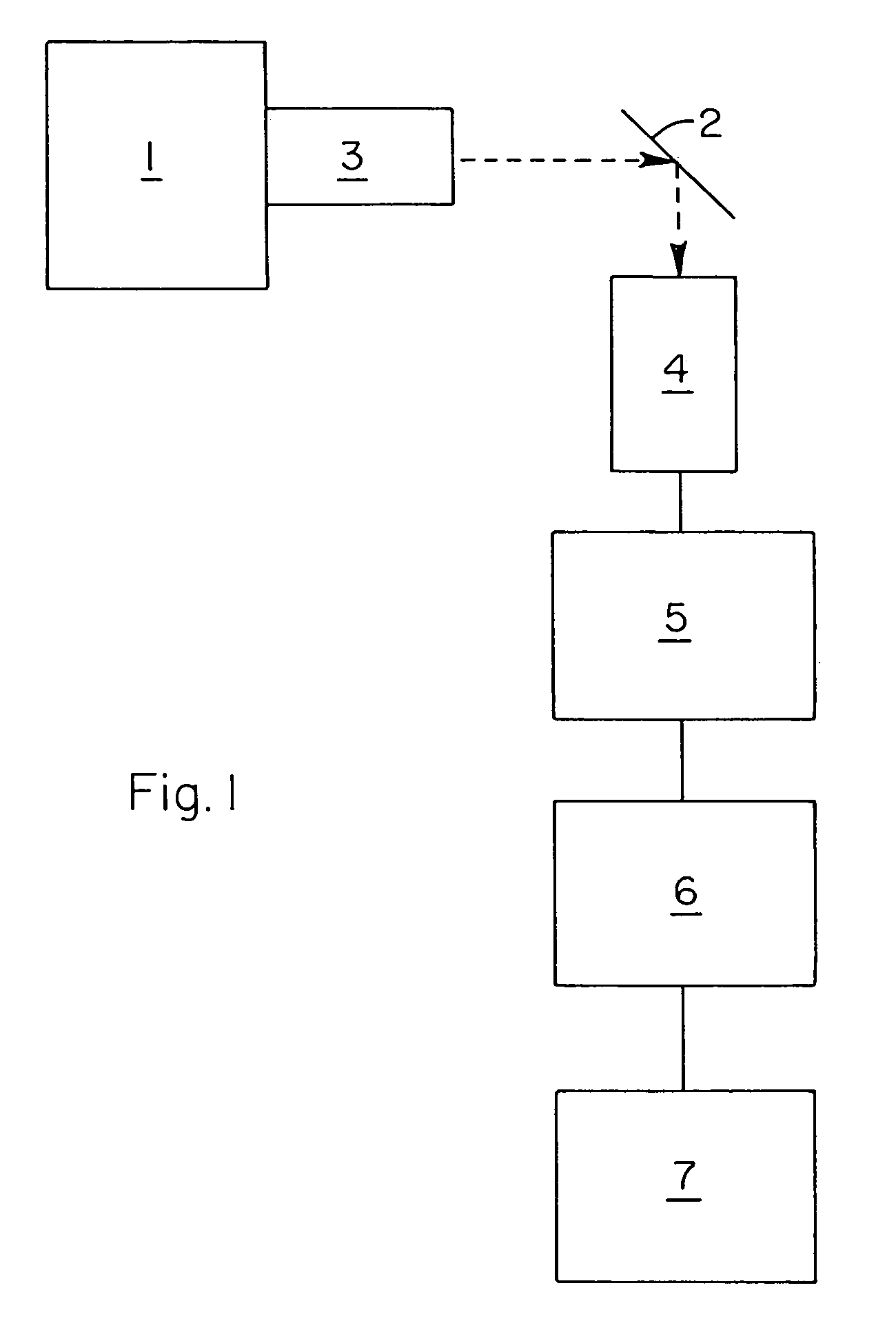
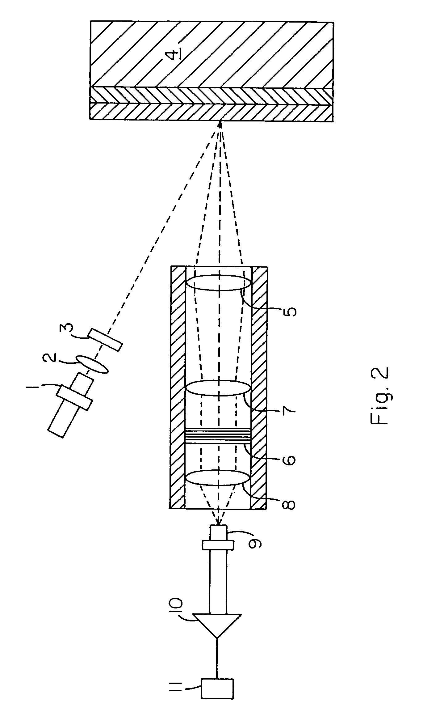
Method used
Image

Examples
example 1
[0088]A NIR fluorophore compound was copolymerized into a sodiosulfopolyester (0.09 mole fraction 5-sodiosulfoisophthalic acid, 0.41 mole fraction isophthalic acid, 0.23 mole fraction cyclohexanedimethanol, 0.27 mole fraction diethylene glycol) at 5000 ppm. The NIR fluorophore compound was Pc-AlOC6H3(CO2CH3)2, where Pc is phthalocyanine.
[0089]A total of 90 grams of this copolymer was compounded into 4.445 kilograms of a poly[ethylene terephthalate] (PET) copolyester containing 32 mole % 1,4-cyclohexanedimethanol on a 30 mm twin screw extruder to generate a 98.8 ppm NIR fluorophore first concentrate.
[0090]A total of 226.8 grams of this first concentrate were physically mixed with 1179 grams of a second concentrate and 3130 grams of the PET copolyester to form a composition having about 4.94 ppm NIR fluorophores. (The second concentrate contained 3.2 wgt % benzoxazinone [a UV absorber] and 96.8 wgt % the PET copolyester.) The resultant mixture was extruded to form a thin target layer ...
example 2
[0095]The experiment was carried out in the same manner as in Example 1, except the NIR fluorophore concentration in the target layer was about half the concentration of Example 1. Specifically, the layers were made of the same materials and quantities as in example 1, except only 113.4 grams (as opposed to 226.8 grams in Example 1) of the first concentrate were physically mixed the second concentrate and the PET copolyester. The results from Example 2 are listed in Table 2.
[0096]
TABLE 2FluorophSatelliteFluorophcurrentcurrentcurrentconcExtruderMPMlayer(nA)(nA)(nA)(ppm)(RPM)(RPM)(mils)Test 1Test 2Test 32.4760467.40.12 0.1250.1082.4720482.60.0550.0490.0442.4730483.90.0710.0650.0612.4710501.30.0220.0230.0182.4730483.80.0460.0520.0462.4720491.40.0260.0330.0352.4710501.20.0210.0220.019
[0097]Data from Table 2 is plotted in FIG. 6. The actual data is shown as the points, while the best fit of the data is shown as the line. The best fit of the fluorescence signal versus layer thickness had ...
PUM
| Property | Measurement | Unit |
|---|---|---|
| wavelengths | aaaaa | aaaaa |
| wavelengths | aaaaa | aaaaa |
| wavelengths | aaaaa | aaaaa |
Abstract
Description
Claims
Application Information
 - Generate Ideas
- Intellectual Property
- Life Sciences
- Materials
- Tech Scout
- Unparalleled Data Quality
- Higher Quality Content
- 60% Fewer Hallucinations
Browse by: Latest US Patents, China's latest patents, Technical Efficacy Thesaurus, Application Domain, Technology Topic, Popular Technical Reports.
© 2025 PatSnap. All rights reserved.Legal|Privacy policy|Modern Slavery Act Transparency Statement|Sitemap|About US| Contact US: help@patsnap.com