Periodic calibration on a communications channel

a communication channel and frequency technology, applied in the field of periodic calibration of communication channels, can solve the problems of difficult to determine the transmit weight vector from the receive weight vector, less than optimal reception at the base station, and received signals that are being processed may be somewhat distorted, etc., to achieve rapid calibration, high accuracy, and easy implementation

Inactive Publication Date: 2005-11-08
INTEL CORP
View PDF150 Cites 119 Cited by
  • Summary
  • Abstract
  • Description
  • Claims
  • Application Information

AI Technical Summary

Benefits of technology

[0045]Still another feature of the invention is calibrating a communication station having an antenna array that the calibrating easy and without taking the communication station off the air for those conventional channels not currently being calibrated.
[0047]Still another feature of the invention is calibrating a communication station, the calibrating method providing high accuracy, with immunity to frequency offset, timing misalignment, I / Q mismatch, and phase noise that typically might occur in communicating with inexpensive subscriber units.
[0048]Another feature of the invention is providing a calibration method and apparatus that can be readily implemented in a radio frequency system and that make it practical to perform frequent and routine system calibration, the calibration enabling the use of a calibrated transmit weight vector, the transmit weight vector essentially determined from a receive weight vector, the calibration including correcting for differences in electronic paths and for differences in RF propagation effects.
[0049]Yet another feature is enabling rapid calibration even several times during an existing call.
[0050]Yet another feature is enabling carrying out calibration in a seamless manner during an ongoing call so that a communication station may be able to continuously calibrate itself during a particular call.
[0052]Yet another feature is providing the ability to determine whether calibration is accurate, for example by performing statistical measurements, together with the ability to feedback such information to the communication station to determine, for example, if the combining from several remote stations may be necessary.

Problems solved by technology

Practical problems may make difficult determining the transmit weight vector from the receive weight vector for a particular user.
However, on the uplink, the received signals that are being processed may be somewhat distorted by the receive electronics (the receive apparatus chains) associated with each of the antenna elements of the antenna array.
A receive weight vector that does not take these receive electronics chain and RF propagation effects into account will be in error, causing less than optimal reception at the base station.
When one transmits downlink signals through the antenna array, each of the signals radiated by an antenna element goes through a different transmit electronics apparatus chain; thus possibly causing different amplitude and phase shifts in the transmitted signals.
If the transmit weight vector was derived from a receive weight vector that did not take the differences in the receive electronics chains and RF propagation into account, transmission from the base station may be hard to achieve.
Further difficulty may result if the transmit weight vector does not take differences in the transmit electronics chains and transmit RF propagation effects into account, possibly making communication using such a transmit weight vector impossible.
Determining the transmit weight vectors from the receive weight vectors for a particular user is more difficult in the case of an FDD system because reciprocity may no longer be assumed.
In general, single calibration factors that are independent of the location of the remote user may not be possible.
Most known methods require external measuring equipment which may be expensive, unwieldy and cumbersome to use repeatedly.
Secondly, conventional calibration methods are sensitive to drifts in system parameters, such as frequency references, over the extended period of time during which measurements are being taken, and these drifts result in inaccuracies in the measured array calibrations.
In addition, some known techniques only determine multiplicative rather than convolution kernel calibrations despite the need to calibrate frequency dependent components in the antenna array.
Still, additional transponder equipment is required.
Second, special waveforms need to be used for that calibration, rather than ordinary communication waveforms supported by standard air interfaces.
This means that the communication station needs additional hardware for forming and transmitting such waveforms, and the calibration station needs special receiving / demodulating hardware, and cannot reuse standard hardware.
Thus there is a chance that a Wachs-like system adapted for use in a wireless communication system may not be allowed to operate in some countries.
Some known methods and systems use special waveforms, and thus need additional hardware for processing such waveforms, and also do not conform to any established air interface standards, so face the risk of not being allowed to operate in some countries Those known systems that also calibrate for the different air paths between the base station antenna elements and the subscriber unit are more properly classified as spatial signature estimating techniques under the definition of calibration used herein.
While the Parish et al. invention enables determining a single set of calibration factors for the base station which enables a downlink set of weights to be determined from an uplink set of weights without requiring some additional apparatus such as a transponder, and calibrates for differences in base station electronics paths, the Parish et al. method cannot be adapted to estimate spatial signatures to deal with RF propagation path differences which may occur.
In addition, the base station needs to enter a spatial calibration mode for carrying out the calibration experiment, and thus cannot be used for any other purpose during that time.
If the calibration information is not accurate, then the beam pattern on the downlink will be highly distorted.
This will have a negative effect on the downlink signal quality and on the downlink range.
Ultimately, a bad calibration strategy may significantly reduce the capacity of the wireless network.

Method used


Image

  • Periodic calibration on a communications channel
  • Periodic calibration on a communications channel
  • Periodic calibration on a communications channel

Examples


Embodiment Construction

A Note on Reference Numerals

[0070]The first one or two digits in a reference numeral indicate on which figure that reference numeral is first introduced. Reference numerals between 100 and 199 are first introduced in FIG. 1, those between 200 and 299 are first introduced in FIG. 2, and so forth. For example, reference numeral 111 is first introduced in FIG. 1, 909 is first introduced in FIG. 9, 1009 is first introduced in FIG. 10, and 1211 is first introduced in FIG. 12.

General System Description

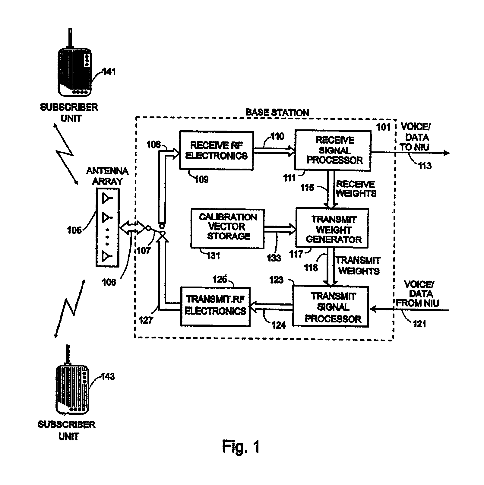
[0071]The invention preferably is implemented in wireless cellular communication systems which include a base station (i.e., a transceiver, a communications station) with a multiple antenna array that uses smart antenna techniques for uplink or downlink communication or both. The preferred implementation is in a system that operates using the Personal Handyphone (PHS) air interface communication protocol. Two implementations are one in which the subscriber units are fixed in location, and th...


PUM


Abstract

Calibration signals can be sent on a traffic channel without interrupting a connection between two radios. In one embodiment, the present invention includes receiving, at a second radio, a first traffic signal transmitted on a traffic channel by a first radio during a first time interval, receiving, at the second radio, a calibration signal transmitted on the traffic channel by the first radio during a second time interval, and receiving, at the second radio, a second traffic signal transmitted on the traffic channel by the first radio during a third time interval, wherein the traffic channel supports a connection between the first and second radios.

Description

CROSS REFERENCE TO RELATED APPLICATIONS[0001]This divisional application claims the benefit of U.S. Provisional Patent Application Ser. No. 60 / 083,875 for Method and Apparatus for Determining Spatial Signatures with Application to Calibrating a Base Station Having an Antenna Array, to inventors Boros, Barratt, Uhlik and Trott, Assignee ArrayComm, Inc., filed May 1, 1998 and the benefit of U.S. patent application Ser. No. 09 / 295,434, for Method and Apparatus for Determining Signatures for Calibrating a Communication Station Having an Antenna Array, to inventors Boros, Barratt, Uhlik and Trott, Assignee ArrayComm, Inc., filed Apr. 20, 1999.FIELD OF INVENTION[0002]This invention relates to the field of wireless communication systems, and more specifically, to a method and apparatus for calibrating a communication station that includes an array of antenna elements.BACKGROUNDSmart Antenna Systems[0003]Antenna arrays may be used in any wireless communication receiver or transmitter or tra...

Claims


Application Information

Patent Timeline
Patent Type & Authority Patents(United States)
IPC IPC(8): H01Q3/26H01Q1/24H04B7/005H04B7/04H04B7/06H04B17/00H04B7/08H04L25/03
CPCH01Q1/246H01Q3/2605H01Q3/267H04B7/005H04B7/0615H04B7/0617H04B7/0848H04L25/03343H04B17/10H04B17/11H04B17/14H04L2025/03426H04B17/12H04B7/0842H04B17/21
Inventor BOROS, TIBORBARRATT, CRAIG H.UHLIK, CHRISTOPHER R.TROTT, MITCHELL D.
Owner INTEL CORP
Why Eureka
Try Eureka