Left ventricular conduits and methods for delivery

a technology of left ventricle and conduit, which is applied in the field of left ventricle, can solve the problems of heart attack, coronary artery disease, impairing the efficiency of heart pumping action, etc., and achieve the effect of facilitating insertion

Inactive Publication Date: 2005-11-15
HORIZON TECH FUNDING CO LLC
View PDF593 Cites 43 Cited by
  • Summary
  • Abstract
  • Description
  • Claims
  • Application Information

AI Technical Summary

Benefits of technology

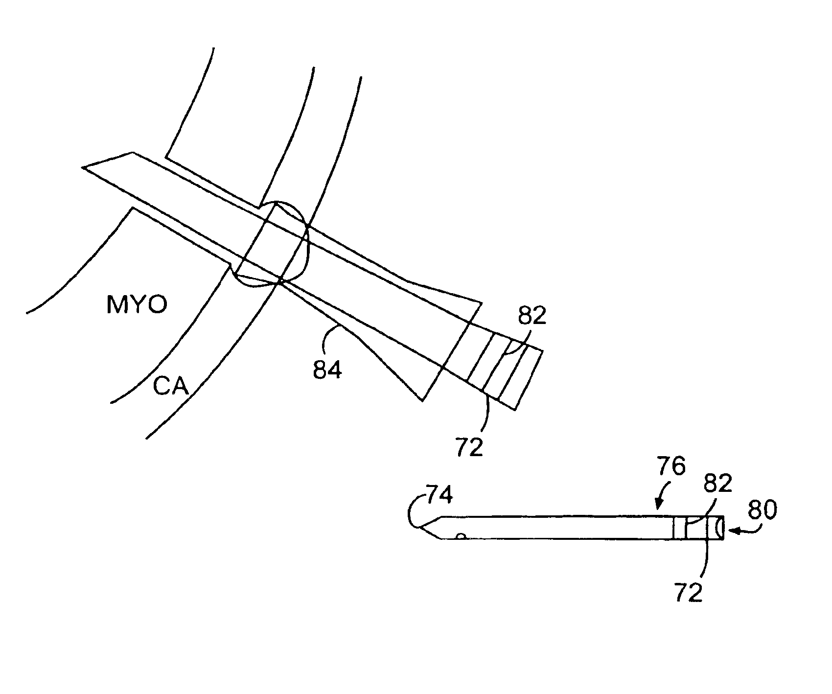
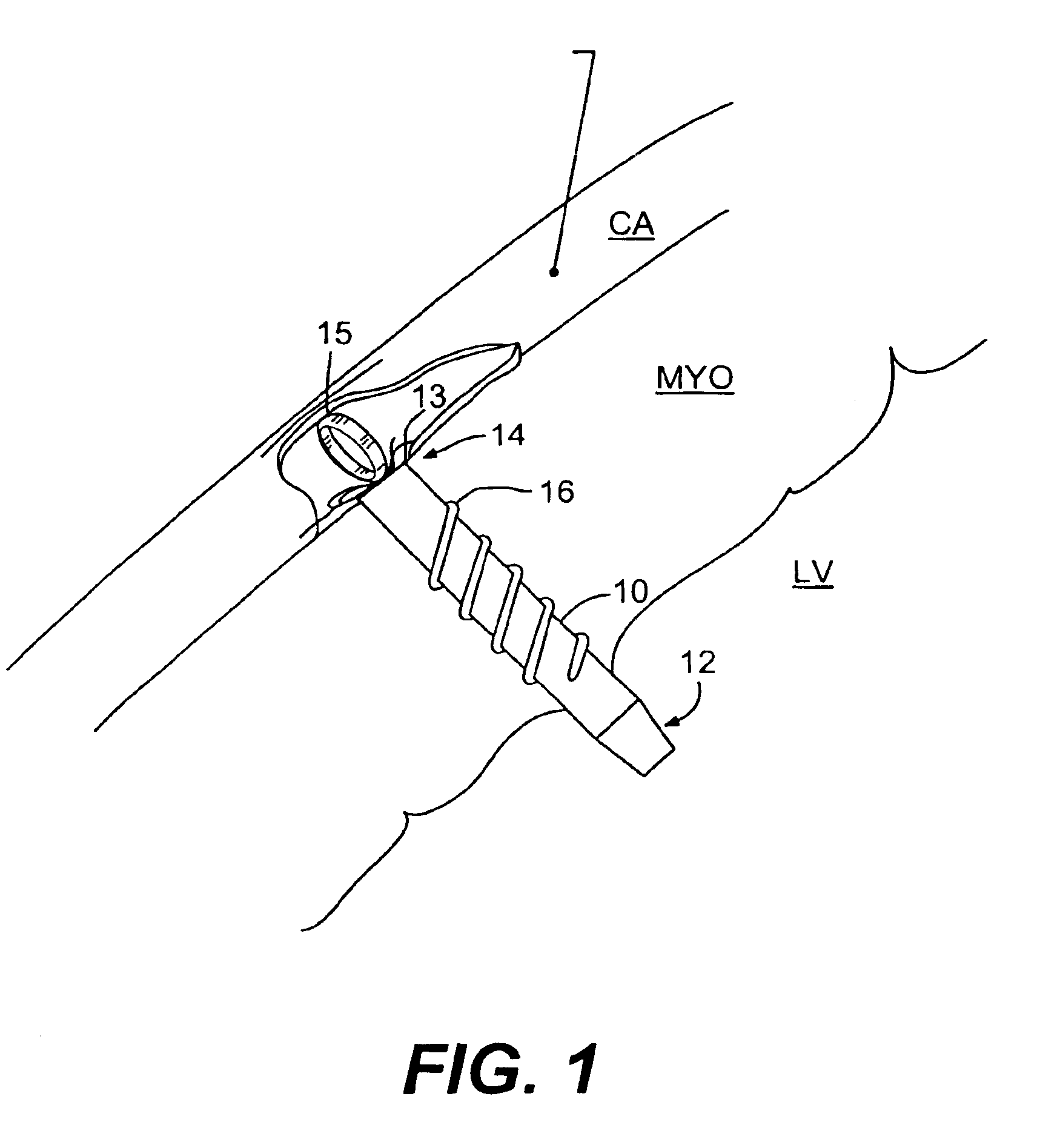
[0008]Briefly stated, the methods and apparatus described and illustrated herein generally relate to direct coronary revascularization, wherein a conduit or opening is provided from the left ventricle to the coronary artery, oftentimes the left anterior descending (LAD), to provide blood flow directly therethrough. These methods and apparatus are particularly useful when a blockage partially or completely obstructs the coronary artery, in which case the bypass conduit or opening is positioned distal to the blockage. More preferably, conduits are provided to direct blood flow from the left ventricle to a coronary artery at a location distal to a blockage in the coronary artery. The conduits may be threaded to facilitate insertion into a patient's heart wall and to control the depth of insertion. Threaded and nonthreaded conduits are preferably delivered

Problems solved by technology

Coronary artery disease is a major problem in the U.S. and throughout the world.
Coronary arteries as well as other blood vessels frequently become clogged with plaque which, at the very least, can reduce blood and oxygen flow to the heart muscle (myocardium), and may impair the efficiency of the heart's pumping action, and can lead to heart attack (myocardial infarction) and death.
In more difficult cases, a surgical bypass of the blocked vessel is necessary.
Such coronary artery bypass graft (CABG) surgery, however, is a ve

Method used


Image

  • Left ventricular conduits and methods for delivery
  • Left ventricular conduits and methods for delivery
  • Left ventricular conduits and methods for delivery

Examples


Embodiment Construction

[0032]As is well known, the coronary artery branches off the aorta and is positioned along the external surface of the heart wall. Oxygenated blood that has returned from the lungs to the heart then flows from the heart to the aorta. Some blood in the aorta flows into the coronary arteries, and the remainder of blood in the aorta flows on to the rest of the body. The coronary arteries are the primary blood supply to the heart muscle and are thus critical to life. In some individuals, atherosclerotic plaque, aggregated platelets, and / or thrombi build up within the coronary artery, blocking the free flow of blood and causing complications ranging from mild angina to heart attack and death. The presence of coronary vasospasm, also known as “variant angina” or “Prinzmetal's angina,” compounds this problem in many patients.

[0033]The principles of the present invention are not limited to left ventricular conduits, and include conduits for communicating bodily fluids from any space within ...


PUM


Abstract

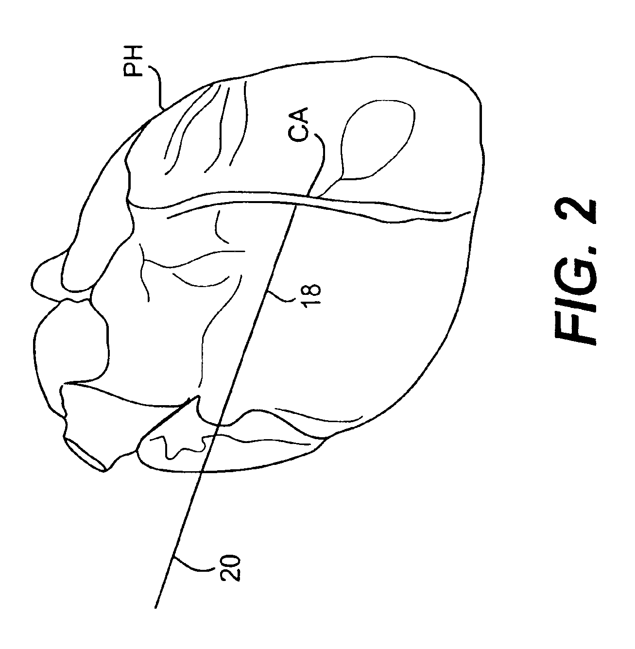
Conduits are provided to direct blood flow from the left ventricle to a coronary artery at a location distal to a blockage in the coronary artery. Threaded and nonthreaded conduits are delivered using a guidewire delivered through the posterior and anterior walls of a coronary artery and into the heart wall. A dilator may be provided over the guidewire into the heart wall, and the conduit delivered over the dilator. An introducer sleeve may be provided over the dilator into the heart wall, the dilator removed, and the conduit delivered through the introducer sleeve. A hollow needle also may be inserted into the posterior and anterior walls of the coronary artery prior to inserting the guidewire. A depth measuring tool may determine the appropriate length of the conduit prior to delivery. The depth measuring tool can include the hollow needle with an access port on a proximal end of the needle and an opening on the distal end of the needle in flow communication with the access port so that when the needle is inserted through the heart wall and into the heart chamber, blood flow through the opening.

Description

CROSS REFERENCE TO RELATED APPLICATIONS[0001]This application is a divisional of U.S. application Ser. No. 09 / 630,385, filed Aug. 1, 2000, now U.S. Pat. No. 6,638,237, which claims the benefits of priority of U.S. Provisional Application No. 60 / 147,211, filed Aug. 4, 1999, both of which are incorporated herein by reference.FIELD OF THE INVENTION[0002]The present invention relates to an apparatus for bypassing a blocked or stenosed blood vessel segment, and, more particularly, to an apparatus and method for delivering a conduit between the coronary artery and the left ventricle of the heart.BACKGROUND OF THE INVENTION[0003]Coronary artery disease is a major problem in the U.S. and throughout the world. Coronary arteries as well as other blood vessels frequently become clogged with plaque which, at the very least, can reduce blood and oxygen flow to the heart muscle (myocardium), and may impair the efficiency of the heart's pumping action, and can lead to heart attack (myocardial infa...

Claims


Application Information

Patent Timeline
IPC IPC(8): A61F2/06A61F2/02A61B17/00A61F2/82A61F2/94A61F11/00
CPCA61F2/2493A61F2/82A61F2/94A61B2017/00252A61F2220/0016A61F2230/0091
Inventor GUILES, MARVINMELSKY, GERALD
Owner HORIZON TECH FUNDING CO LLC
Why Eureka
Try Eureka