Planar reference electrode

a reference electrode and planar technology, applied in the direction of liquid surface applicators, instruments, coatings, etc., can solve the problems of long operational life, unstable potential, and high operating cost of laboratory-based instruments

Inactive Publication Date: 2005-11-15
CHA GEUN SIG
View PDF15 Cites 13 Cited by
  • Summary
  • Abstract
  • Description
  • Claims
  • Application Information

AI Technical Summary

Problems solved by technology

However, the samples collected from remote sampling sites often require special pretreatment to prevent them from contamination or degradation during transportation to the laboratories.
The laboratory-based instruments is expensive to operate, and should be managed by the technicians specially trained in the area.
Numerous schemes have been proposed to accomplish miniaturized working electrodes, and many of them are now commercially available, while reference electrodes have not been extensively developed for miniaturization thereof.
Unfortunately, the presoaking time for this reference system takes more than an hour and the potential is unstable, although it provides long operational lifetime.
However, the formation of a small exposure, which is typically a few micrometers, in the process of mounting an outer membrane is not easy and often results in malfunction of the reference electrode system due to the sealed pore.
In addition, there is a possibility that large particulates contained in sample may block the junction.
Such an abnormality can not be predicted in advance and lowers the reliability of the measurement.
However, to deposit the potassium perchlorate layer, this system requires a well (diameter 2 mm, and height 1.5 mm) affixed on the chip and is not suitable for mass fabrication.

Method used


Image

  • Planar reference electrode
  • Planar reference electrode
  • Planar reference electrode

Examples


example 1

Preparation 1 of the Planar Reference Electrode

[0119]The reference electrode of the present invention was prepared according to the method described below by using porous cotton thread as junction material.

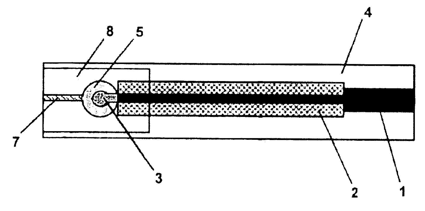
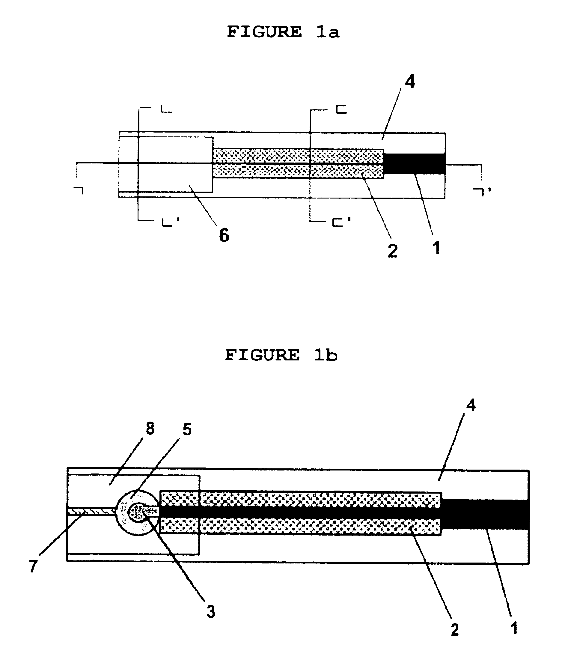
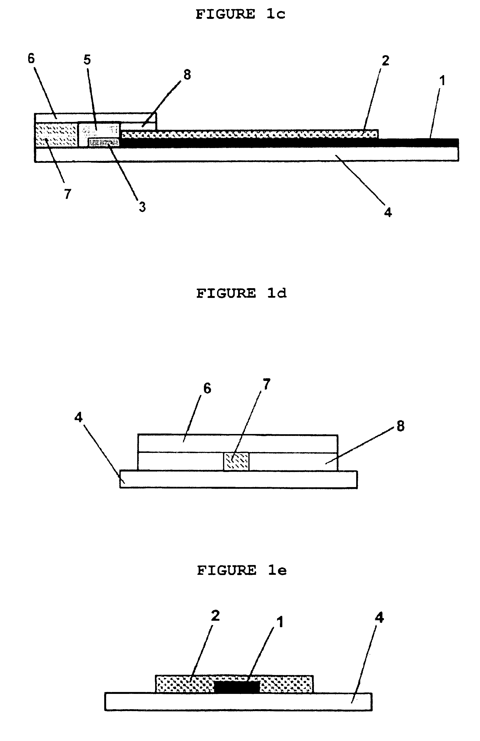
[0120]First, electric conducting line was built onto the polyester plate (4) by using the conventional screen printing method with silver paste from the region of electrode site (3) and electrode connection part (1). Then insulating membrane (2) layer onto the metal conductor (3) excluding the electrode site and electrode connection part (1) was formed by using the typical screen printing method employing an insulating paste.

[0121]The above electrode (3) was placed in 0.0175 M concentration of FCl3 solution for 20-30 minutes to form insoluble metal salt layer, AgCl, onto the electrode site (3).

[0122]The polyester was cut out in a size that can cover the electrode site and then punched to form a well (6 mm diameter) that can hold inner reference solution. From one end of the well t...

example 2

Preparation 2 of the Planar Reference Electrode

[0126]The reference electrode was prepared according to the method as described in example 1 by using porous glass fiber (Whatman international Ltd., Maidstone, England) as junction material instead of cotton thread.

example 3

Preparation 3 of the Planar Reference Electrode

[0127]The reference electrode was prepared according to the method as described in example 1 by using porous cellulose nitrate (Whatman international Ltd., Maidstone, England) as junction material instead of cotton thread.


PUM

PropertyMeasurementUnit
heightaaaaaaaaaa
weight %aaaaaaaaaa
diameteraaaaaaaaaa

Abstract

The present invention disclose a method for fabricating planar reference electrodes. Particularly, the present invention relates to the planar reference electrode comprising plate (4); electrode connection (1); electrode (3); insulating membrane (2); inner reference solution (5); junction (7 or 9); and protecting membrane (6, 8 or 9), and processes for fabrication thereof, in which the junction is composed of porous material such as cotton thread, glass fiber, cellulose nitrate, cellulose acetate, filter paper and any material that can produce capillary action; porous polymer membrane; or a capillary either directly printed on the substrate or inserted with a thin film. The planar reference electrode of the present invention exhibit stable electric potential and short activation period, and may be used in both potentiometry and voltammetry. The planar reference electrodes of the present invention can be easily miniaturized and mass produced.

Description

FIELD OF THE INVENTION[0001]The present invention relates to a planar reference electrode and a process for fabrication thereof and more specifically to the reference electrode including substrate (4); electrode connection part (1); electrodes formed on the plate (3); insulating membrane (2); inner reference solution (5); junction (7 or 9); and protecting membrane (6, 8 or 9), in which the junction comprises porous material such as cotton thread, glass fiber, cellulose nitrate, cellulose acetate, filter paper; polymer-based porous membrane; or capillary type.BACKGROUND OF THE INVENTION[0002]Electrochemical methods such as potentiometry or voltammetry have been commonly applied in the analytical laboratories to determine specific chemical components contained in clinical, environmental or industrial samples. However, the samples collected from remote sampling sites often require special pretreatment to prevent them from contamination or degradation during transportation to the labora...

Claims


Application Information

Patent Timeline
Patent Type & Authority Patents(United States)
IPC IPC(8): G01N27/30G01N27/31
CPCG01N27/301G01N27/31
Inventor CHA, GEUN SIGCUI, GANGYOO, JINALEE, JOUNG SUNAM, HAKHYUN
Owner CHA GEUN SIG
Why Eureka
Try Eureka