System and method for determining integrated circuit logic speed

a logic speed and integrated circuit technology, applied in the direction of pulse automatic control, error detection/correction, instruments, etc., can solve the problems of complex ring oscillator approach, high layout dependence, and variance in operating voltage, so as to achieve easy measurement, increase delay time, and increase granularity

Inactive Publication Date: 2005-11-15
ADAPTEC +1
View PDF7 Cites 19 Cited by
  • Summary
  • Abstract
  • Description
  • Claims
  • Application Information

AI Technical Summary

Benefits of technology

[0016]The delay logic of the embodiments of the present invention increases the delay time between asserting the reset signal and the actual reset of the last scan cell storage element such that it is easily measurable, with more granularity. Because the delay logic increases the delay time such that it is easily measurable with more granularity, embodiments of the present invention advantageously can correlate ICs within a particular process, into various speed grades.

Problems solved by technology

However, the speed of the logic gates can vary from one IC to another because of silicon manufacturing process variances.
Moreover, variances in operating voltage can affect the speed of an IC.
Unfortunately, the ring oscillator approach is complicated and highly layout dependent.
These determinations require a great deal of planning and experimentation to generate the desired results.
Unfortunately, several problems are associated with the approach.
First, the composition of the test vector must be well planed in order for proper testing, thus again requiring a great deal of planning and experimentation to generate the desired results.
Second, the testor used to test the IC must be able to drive the inputs and measure the outputs of the IC fast, often faster than many testor can operate.
Third, the determination of the whether the test passed or failed is often difficult to establish, and further passing or failing only provides one threshold for sorting IC devices.
For example, if parts A, B, and C all pass, there is no way to determine the relationships between the parts and there is no way to relate their passing to simulations.
Moreover, there is no way to determine how fast the parts are or how slow they are.

Method used


Image

  • System and method for determining integrated circuit logic speed
  • System and method for determining integrated circuit logic speed
  • System and method for determining integrated circuit logic speed

Examples


Embodiment Construction

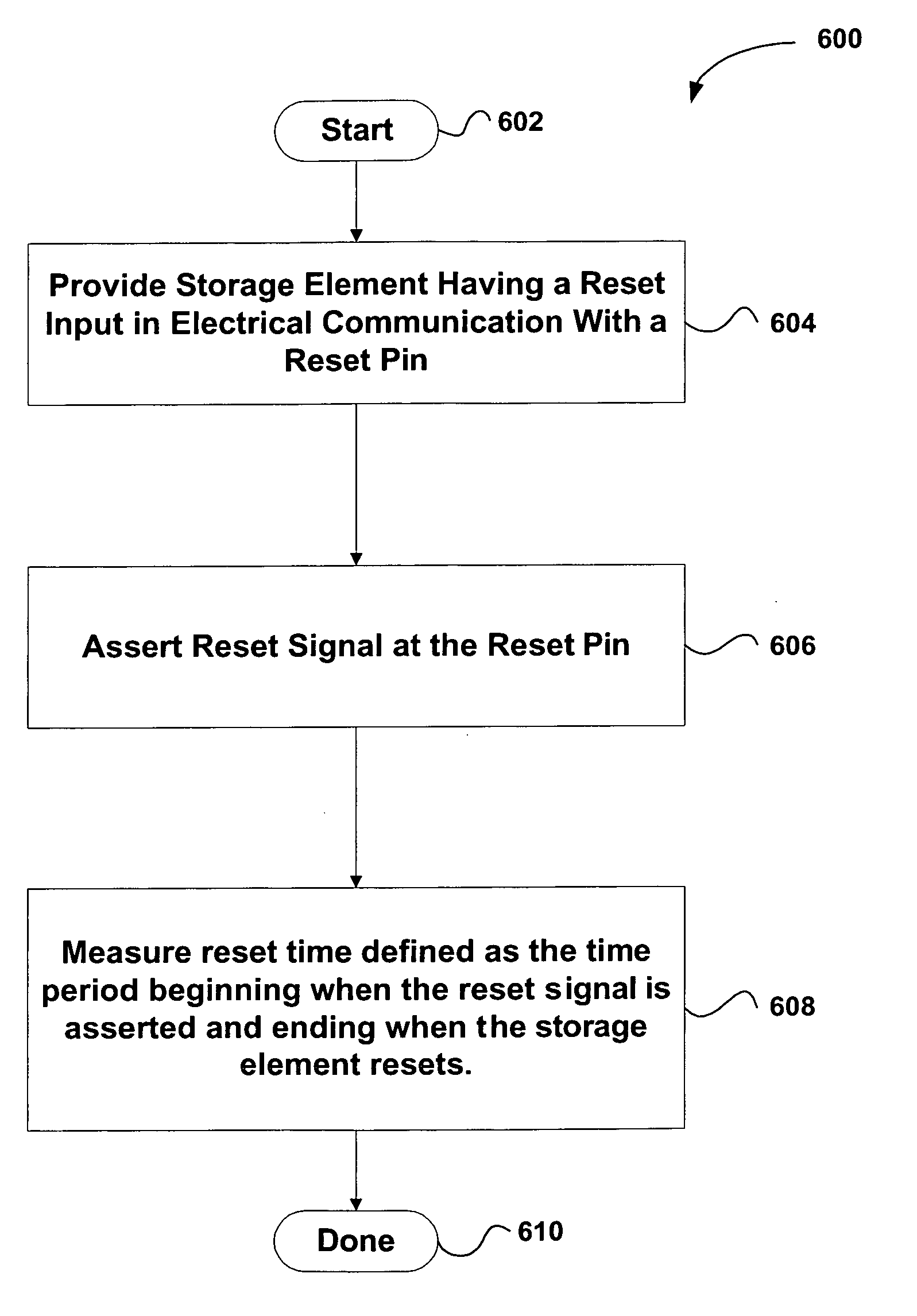
[0026]An invention is disclosed for determining IC logic speed using an asynchronous reset signal having a predetermined delay applied before connecting to a final scan flop of a scan chain. In this manner, an accurate IC speed can be determined based on the time period occurring before the final scan flop resets. In the following description, numerous specific details are set forth in order to provide a thorough understanding of the present invention. It will be apparent, however, to one skilled in the art that the present invention may be practiced without some or all of these specific details. In other instances, well known process steps have not been described in detail in order not to unnecessarily obscure the present invention.

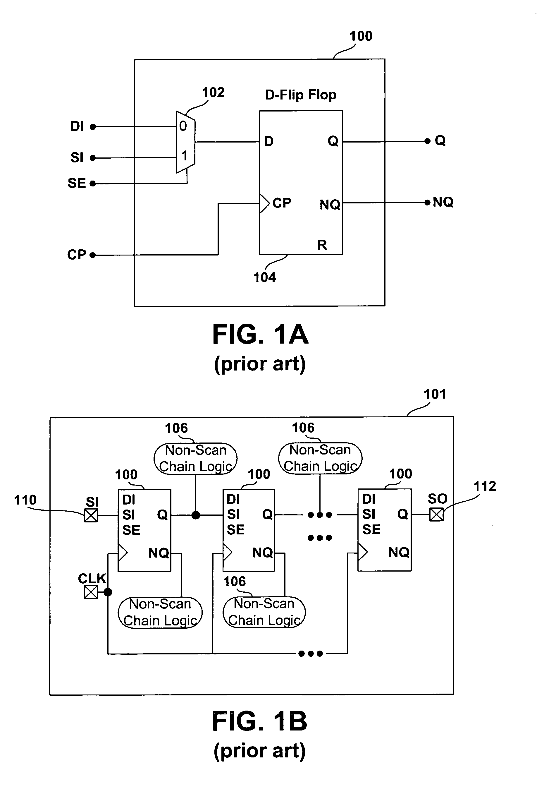
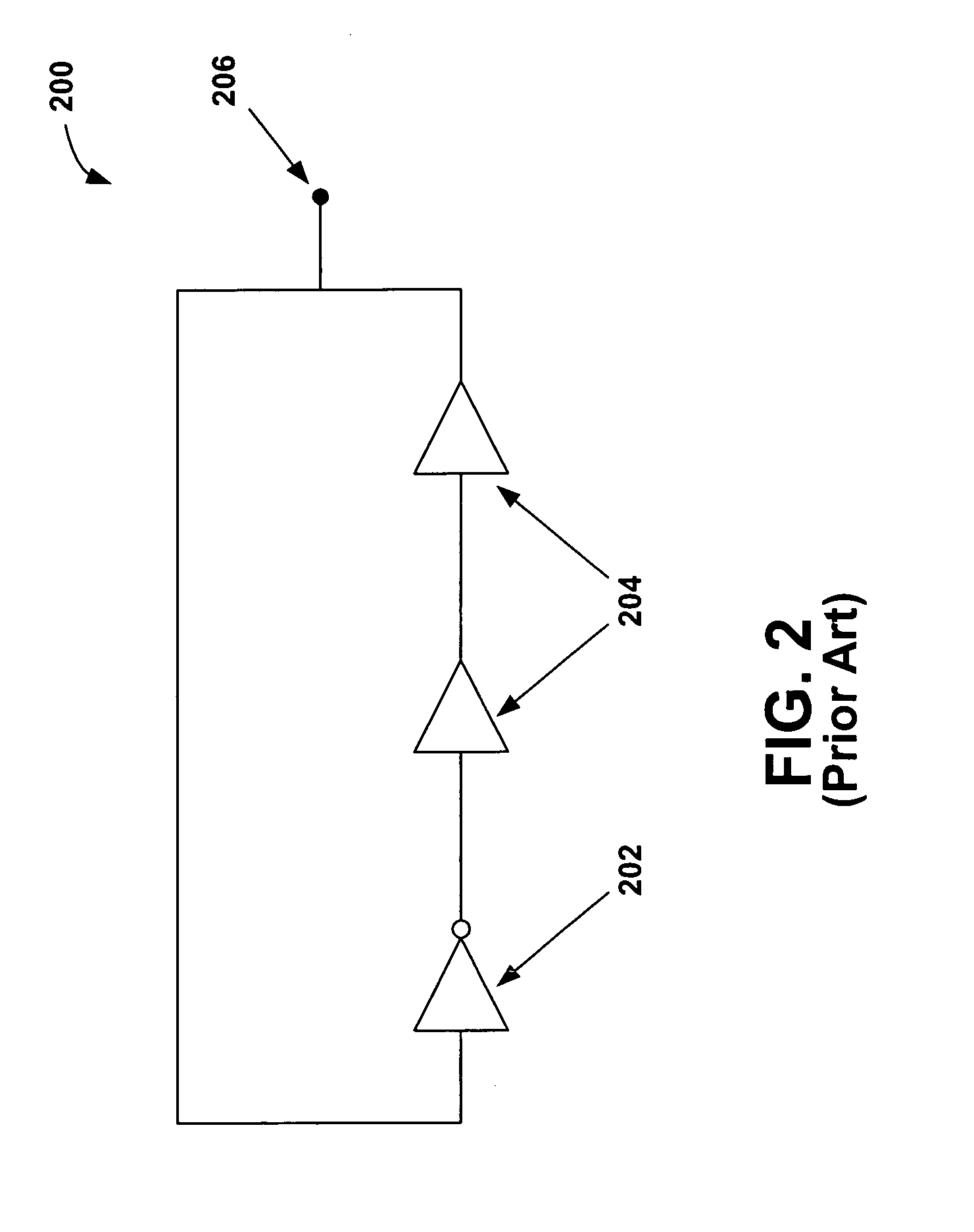
[0027]FIGS. 1A, 1B, and 2 were described in terms of the prior art. FIG. 3 is a schematic diagram showing a scan flop 300 configured for asynchronous reset, in accordance with an embodiment of the present invention. The scan flop 300 includes a multiplex...


PUM


Abstract

An invention is disclosed for determining integrated circuit (IC) logic speed. A storage element is provided that includes a reset input in electrical communication with a reset pin. A reset signal is then asserted at the reset pin, and a reset time is measured. The reset time is defined as the time period beginning when the reset signal is asserted and ending when the storage element resets. In this manner, the reset time can be used to determine a speed of the IC logic relative to a process. In one aspect, delay logic is provided that is in electrical communication with the reset pin and in electrical communication with the storage element. In this aspect, the delay logic delays the reset signal for a predetermined time period. Optionally, the reset time can be compared to a predetermined fast corner reset time and a predetermined slow corner reset time. Further, the IC logic speed can be correlated to a simulation using the embodiments of the present invention.

Description

BACKGROUND OF THE INVENTION[0001]1. Field of the Invention[0002]This invention relates generally to integrated circuit testing, and more particularly to methods for determining logic speed in integrated circuits.[0003]2. Description of the Related Art[0004]Integrated circuits (ICs) are the cornerstones of myriad computational systems, such as personal computers and communications networks. As such, purchasers of such systems have come to expect significant improvements in speed performance over time, which encourages system designers to select ICs that guarantee superior speed performance. In an effort to increase chip speed, quality, and density of internal circuit components, chip manufacturers often attempt to maximize fault coverage when testing their IC designs. A common industry design practice is to make the IC design scannable by implementing scan cells. Among many types of scan cells, the most common scan cell is the “muxed-scan,” or also referred to herein as a “scan flop....

Claims


Application Information

Patent Timeline
Patent Type & Authority Patents(United States)
IPC IPC(8): G01R31/00G11C8/00H03L7/00G01R31/3185G11C29/50
CPCG01R31/318541G01R31/318594G11C29/50G11C29/50012
Inventor STENFORT, ROSSCHI, TIANSHU
Owner ADAPTEC
Why Eureka
Try Eureka