Superconducting magnet for MRI

a superconducting magnet and magnetic resonance technology, applied in the direction of superconducting magnets/coils, magnetic bodies, instruments, etc., can solve the problems of patient feeling cooped up, imaging devices failing to perform their functions, etc., to achieve stable cooling of superconducting coils, reduce material cost and transport cost, and high thermal conductivity

Inactive Publication Date: 2005-11-22
HITACHI LTD
View PDF6 Cites 17 Cited by
  • Summary
  • Abstract
  • Description
  • Claims
  • Application Information

AI Technical Summary

Benefits of technology

[0006]The present invention has an object of reducing a manufacturing cost of a superconducting MRI magnet by simplifying a cooling structure and of providing the superconducting MRI magnet that will not be quenched even when a mounted refrigerator is stopped for a certain period of time.
[0012]Thermally connecting the thermal anchors between the superconducting coils and liquid helium can stably cool the superconducting coils even when the level of liquid helium in the liquid receiver is low. This in turn enables the liquid receiver to be reduced in volume, resulting in a reduction in the material cost and transport cost. Further, by replacing the liquid tank with that of high thermal conductivity, the thermal anchors and the heat exchanger can be shortened in length, resulting in a cost reduction. Further, by providing a construction of cooling the superconducting coils through the thermal anchors, it is possible to build a cooling system that prevents the superconducting magnet from being quenched for a predetermined period even when the refrigerator stops.

Problems solved by technology

Conventionally, a horizontal cylindrical superconducting coil has been used as a superconducting MRI magnet but there is a problem that a patient feels being cooped up.
Conventional superconducting MRI magnets have a problem that, while the refrigerator is stopped, the superconducting magnet is quenched, and an MRI imaging device fails to perform its function and becomes unavailable.

Method used


Image

  • Superconducting magnet for MRI
  • Superconducting magnet for MRI
  • Superconducting magnet for MRI

Examples


Embodiment Construction

[0023]Now, embodiments of the invention will be described with reference to accompanying drawings.

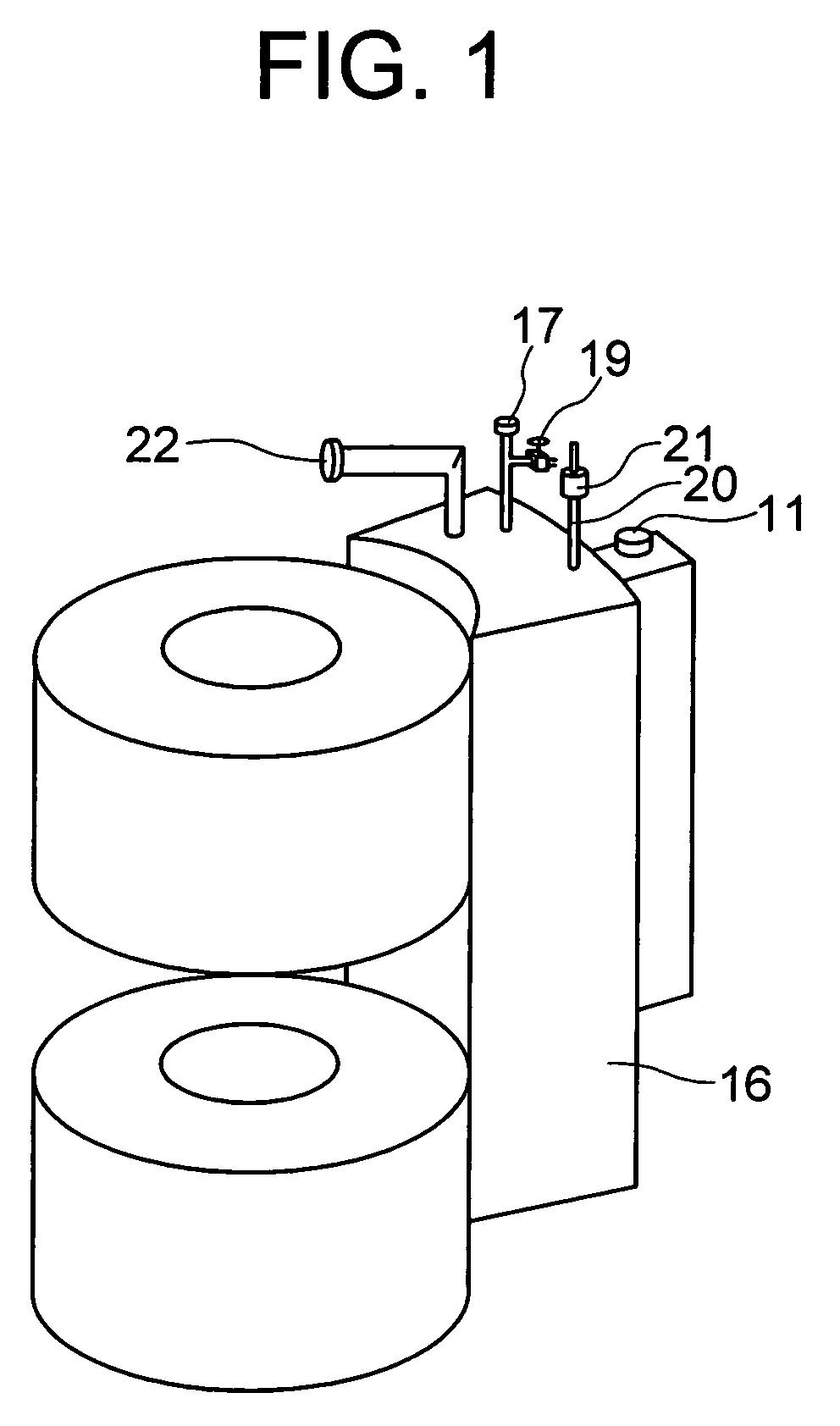
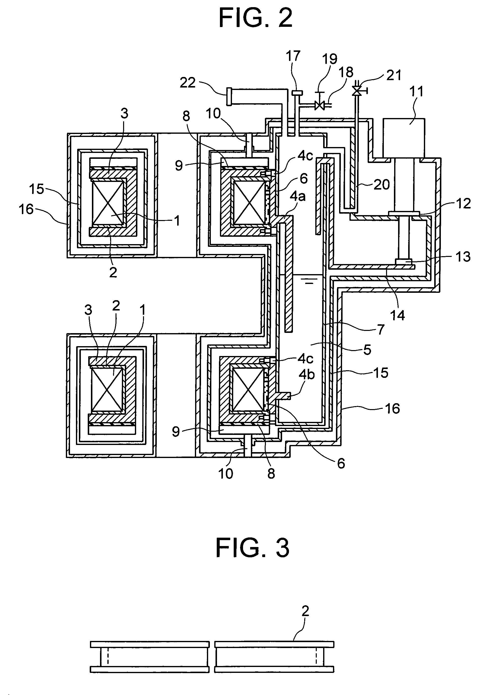
[0024]FIG. 1 is an overall external view showing an example of a conduction cooling type superconducting MRI magnet according to the invention. FIG. 2 shows a cross section of the superconducting MRI magnet of FIG. 1.

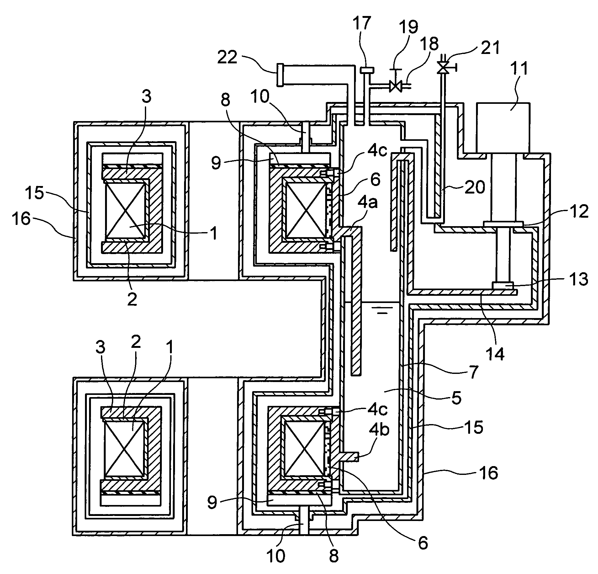
[0025]As shown in FIG. 1, the superconducting MRI magnet according to the invention has two doughnut-shaped vacuum containers 16, each accommodating a superconducting coil, arranged in such a manner as to face each other vertically. A square column-shaped vacuum container 16 connecting the two doughnut-shaped vacuum containers 16 has a liquid helium receiver installed therein. A refrigerator 11 is mounted on the square column-shaped vacuum container 16.

[0026]Referring to the cross section of FIG. 2, the superconducting coils 1 of the superconducting magnet are wound on coil conduction members 2. The coil conduction members 2 are fitted in coil frames 3. Stresses generated a...


PUM

PropertyMeasurementUnit
thicknessaaaaaaaaaa
temperatureaaaaaaaaaa

Abstract

The invention utilizes a characteristic of superconducting coils that they have high thermal conductivity in a direction of winding. A part of the superconducting coils is thermally connected with liquid helium through thermal anchors so that the part of the superconducting coils can be cooled to the liquid helium temperature. This cooling structure maintains thermal stability of a superconducting MRI magnet even in a condition that a refrigerator stops for a certain period of time, and reduces a manufacturing cost of the superconducting magnet.

Description

BACKGROUND OF THE INVENTION[0001]The present invention relates to a superconducting magnet for MRI and more particularly to a cooling structure therefor.[0002]A superconducting magnet for MRI (Magnetic Resonance Imaging) is designed to produce a uniform magnetic field in a space defined between upper and lower doughnut-shaped, superconducting coils. In a hospital a patient is laid between the upper and lower superconducting coils to examine his or her internal organs and the like. Conventionally, a horizontal cylindrical superconducting coil has been used as a superconducting MRI magnet but there is a problem that a patient feels being cooped up. An MRI system using two superconducting coils, situated at upper and lower positions, is called an “open type” because a space opening in a horizontal direction is formed by the upper and lower superconducting coils. This “open type” MRI system is well received by doctors and patients since it gives little intimidatory feeling and oppressiv...

Claims


Application Information

Patent Timeline
Patent Type & Authority Patents(United States)
IPC IPC(8): G01R33/38G01R33/3815H01L39/04H01F6/00H01F6/04
CPCG01R33/3806G01R33/3815
Inventor NEMOTO, TAKEOWATANABE, HIROYUKI
Owner HITACHI LTD
Why Eureka
Try Eureka