
Projectile launch detection system utilizing a continuous wave radio frequency signal to confirm muzzle exit

a projectile launch detection and radio frequency signal technology, applied in the field of gun-launched projectiles, can solve the problems of preventing the operation of the second safety feature, difficult to implement conventional approaches for detecting the second safety signature on the projectile, and not experiencing measurable spin during the gun launch. achieve the effect of improving performance reliability

Inactive Publication Date: 2005-11-22
UNITED STATES OF AMERICA THE AS REPRESENTED BY THE SEC OF THE ARMY
View PDF4 Cites 17 Cited by
  • Summary
  • Abstract
  • Description
  • Claims
  • Application Information

AI Technical Summary

Benefits of technology

[0010]A projectile launch detection system (referred to herein as “the system” or “the present system”) utilizes a continuous wave radio frequency signal to confirm muzzle exit. The present system can be used in smoothbore, fin-stabilized, non-air breathing projectiles. The present system is encased entirely within the fuze housing. Furthermore, the present system utilizes the basic building blocks of a proximity sensor system. Consequently, the present system can serve a dual purpose of proximity sensing and launch detection. The present system is encapsulated, protecting the present system from the launch environment and improving performance reliability.

Problems solved by technology

However, fin-stabilized projectiles such as mortars and tank ammunition do not experience measurable spin during gun launch.
The conventional approaches for detecting the second safety signature are difficult to implement on projectiles that do not or can not breathe air from the air stream during launch, use fixed-fin tail assemblies, or do not have an umbilical connection to a weapon platform.
For projectiles that can breathe air from the air stream during launch, ports for diverting the air stream through the launch detector can become clogged, preventing operation of the second safety feature.
The need for such a system has heretofore remained unsatisfied.

Method used


Image

  • Projectile launch detection system utilizing a continuous wave radio frequency signal to confirm muzzle exit
  • Projectile launch detection system utilizing a continuous wave radio frequency signal to confirm muzzle exit
  • Projectile launch detection system utilizing a continuous wave radio frequency signal to confirm muzzle exit

Examples


Embodiment Construction

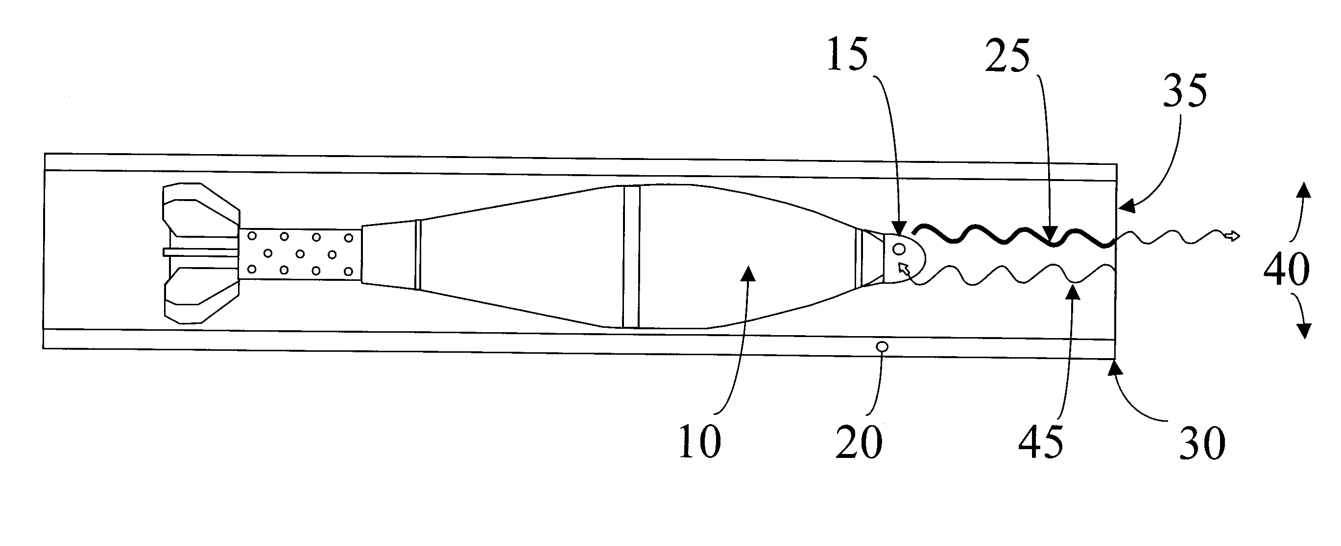
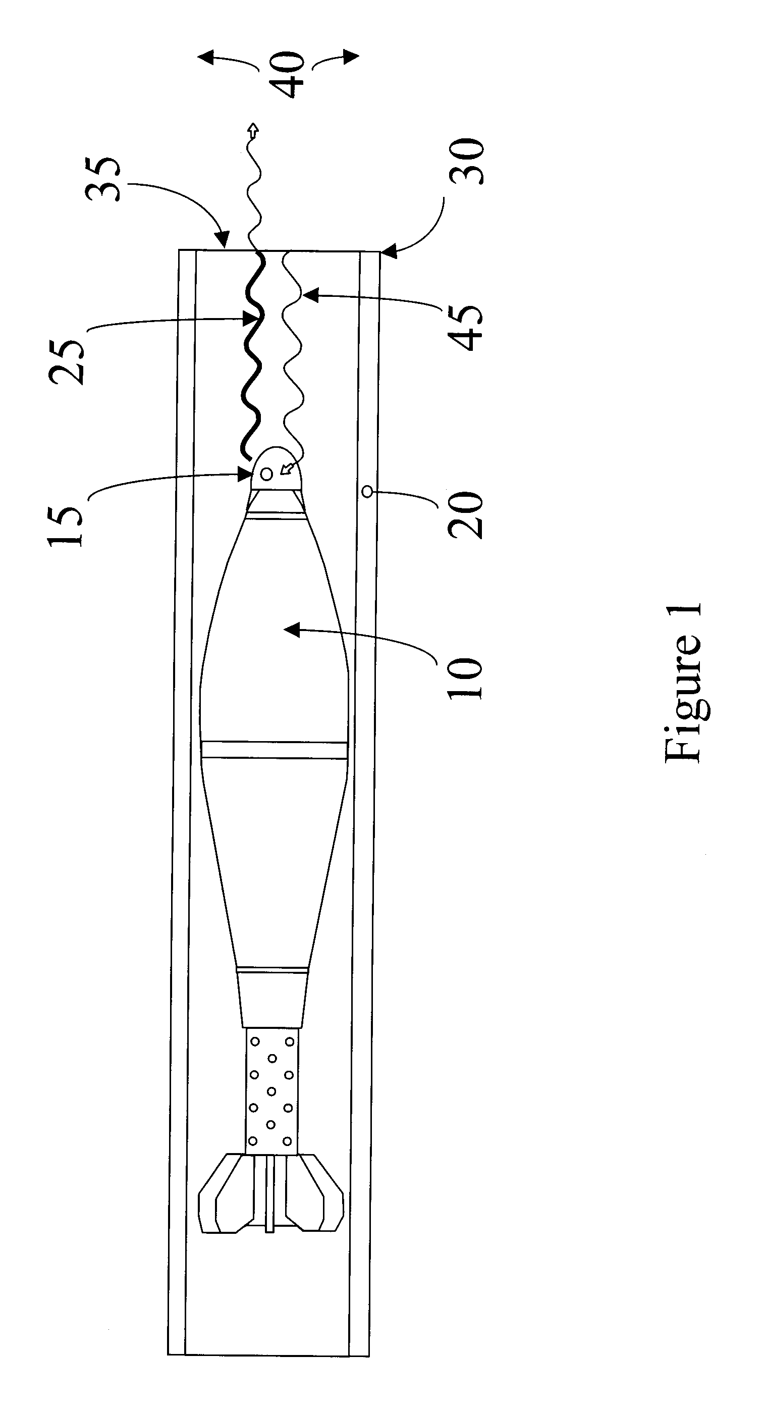
[0022]FIG. 1 illustrates an exemplary mortar projectile 10 (further referenced herein as projectile 10) comprising a projectile launch detection system 15 (further referenced herein as system 15) that utilizes a continuous wave radio frequency signal to detect a launch of projectile 10 from a gun tube 20. System 15 transmits a continuous wave radio frequency signal 25 down the gun tube 20 toward a muzzle 30 of the gun tube 20. Gun tube 20 appears to the continuous wave radio frequency signal 25 as a circular waveguide. A boundary 35 at the muzzle 30 between the gun tube 20 and free space 40 reflects a portion of the continuous wave radio frequency signal 25 as the reflected continuous wave radio frequency signal 45.

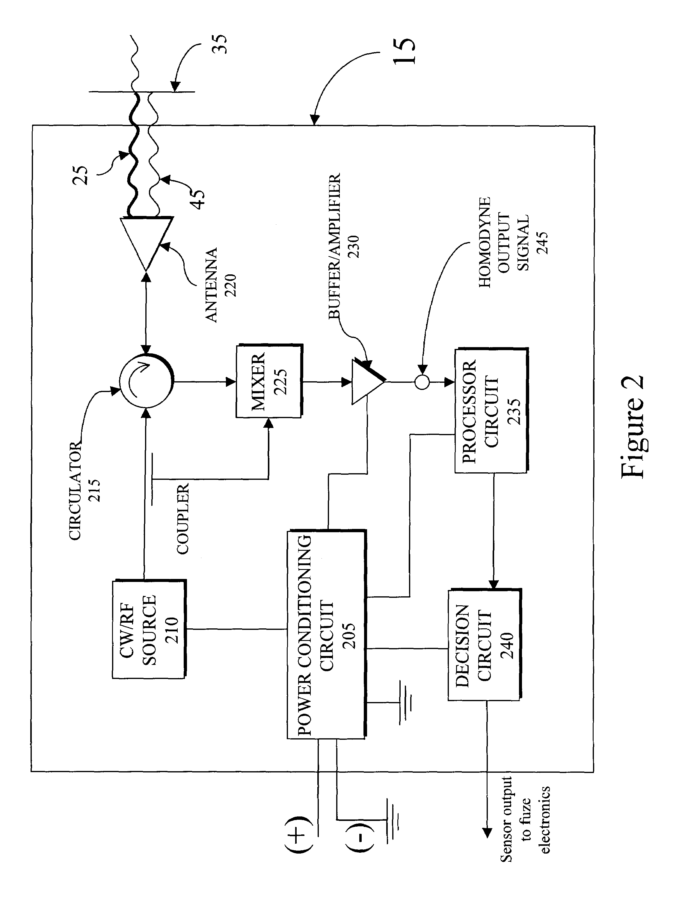
[0023]System 15 comprises a power supply 205, a continuous wave radio frequency (CW / RF) source 210, a circulator 215, an antenna 220, a mixer 225, a buffer / amplifier 230, a processing circuit 235, and a decision circuit 240. The power supply 205 supplies regulated electri...


PUM


Abstract

A projectile launch detection system utilizes a continuous wave radio frequency signal (CW / RF) to confirm muzzle exit. The projectile launch detection system can be used in smoothbore, fin-stabilized, non-air breathing projectiles. The gun tube appears as a waveguide to the projectile launch detection system during projectile launch. The projectile launch detection system transmits a CW / RF signal down the gun tube during launch of the projectile. A portion of the CW / RF signal is reflected back by an impedance mismatch at the boundary between the muzzle of the gun tube and free space. Upon exit by the projectile from the gun tube, an exit signature is detected that is defined by the impedance of the gun tube and by a ratio of the diameter of the gun tube to the frequency of the CW / RF signal. The projectile launch detection system processes the exit signature to detect a muzzle launch of the projectile from a specific gun tube.

Description

CROSS REFERENCE TO RELATED APPLICATIONS[0001]This application claims benefit under 35 USC 119(e) of provisional application 60 / 320,171, filed May 7, 2003, the entire file wrapper contents of which provisional application are herein incorporated by reference as though fully set forth at length.FEDERAL RESEARCH STATEMENT[0002]The inventions described herein may be manufactured, used and licensed by or for the U.S. Government for U.S. Government purposes.BACKGROUND OF INVENTION[0003]1. Field of the Invention[0004]The present invention generally relates to gun-launched projectiles, and in particular to a method for detecting a launch using a projectile borne continuous wave radio frequency signal in which the detection of the launch is used to arm a fuze in a gun-launched projectile.[0005]2. Background of the Invention[0006]Gun-launched projectiles utilize a safety and arming (S&A) device within a fuze to arm a projectile after launch. The projectile is considered armed when the fuze be...

Claims


Application Information

Patent Timeline
Patent Type & Authority Patents(United States)
IPC IPC(8): G01S13/00
CPCF42C15/40F42C15/44
Inventor WARDELL, RONALD G.NICKEL, JOHN I.WARD, DENNIS W.
Owner UNITED STATES OF AMERICA THE AS REPRESENTED BY THE SEC OF THE ARMY
Learn More