Turbo-charged internal combustion engine with in-cylinder EGR and injection rate shaping

a technology of internal combustion engine and injection rate shaping, which is applied in the direction of valve drives, non-mechanical valves, tractors, etc., can solve the problems of high engine heat rejection, inability to reduce the amount of air available for combustion, and inefficient or incomplete combustion of unburned hydrocarbons and carbon monoxide, etc., to achieve the effect of improving the efficiency of the turbocharger

Inactive Publication Date: 2005-11-29
VOLVO LASTVAGNAR AB
View PDF66 Cites 24 Cited by
  • Summary
  • Abstract
  • Description
  • Claims
  • Application Information

AI Technical Summary

Benefits of technology

[0021]In several aspects, the invention may provide post bump shutoff with a lash adjustment mechanism, improved turbo-charger efficiency, a modified post bump injection system, and in-cylinder exhaust gas recirculation with and without post bump shutoff capability. Camless or variable valve timing and lift technologies may be used to shape the post bump to match the region where exhaust port pressure is higher than intake port pressure. In addition, these technologies may provide post bump shutoff capability. Various air systems (shown in FIGS. 5, 6, 7A, 7B, and 11) can be used to overcome lack of airflow (A / F) at low engine speeds with a fixed timing and duration post bump without the shutoff capability.
[0023]In another aspect, the Invention provides a combination of in-cylinder EGR and injection rate shaping with a fixed geometry turbo-charger that may be optimally matched for low speed engine operation and good transient response.

Problems solved by technology

Unburned hydrocarbons and carbon monoxide tend to be produced by inefficient or incomplete combustion.
Efficient, complete combustion, on the other hand, tends to produce oxides of nitrogen.
Controlling the amounts of emissions produced by an internal combustion engine, then, becomes an issue of balancing combustion efficiency against raising combustion temperatures high enough to produce oxides of nitrogen.
Since compression-ignition engines need to run with an excess of air to avoid emitting particulates, reducing the production of oxides of nitrogen by reducing the amount of air available for combustion is not a practical solution.
External EGR, however, relies on high engine heat rejection to work, since the post-combustion gases must travel a relatively long way.
Also, the valves and other hardware associated with external EGR increase the cost and complexity of the engine.
Furthermore, if the external EGR is plumbed through the intake manifold, it may be difficult to control the amount of exhaust gas that is re-admitted to each individual combustion chamber.
This may pose a problem if, e.g. some combustion chambers run hotter than other combustion chambers, such as those that are nearer the water jacket exit.
The EGR valve, along with the associated actuator and control hardware, is also a point of potential failure, jeopardizing the durability of the engine.
Sometimes, under operating conditions such as at start-up or low-speed operation, an engine does not produce enough post-combustion gases to drive the compressor adequately.
Although every point within a diesel engine combustion chamber should be at or above the kindling temperature of the fuel when fuel is admitted to the combustion chamber, this may not always be the case.
The fuel itself may, e.g. be cold relative to the combustion chamber, especially during winter driving.
Cold fuel may thus reduce the temperature locally in the combustion chamber below the kindling temperature of the fuel.

Method used


Image

  • Turbo-charged internal combustion engine with in-cylinder EGR and injection rate shaping
  • Turbo-charged internal combustion engine with in-cylinder EGR and injection rate shaping
  • Turbo-charged internal combustion engine with in-cylinder EGR and injection rate shaping

Examples


first embodiment

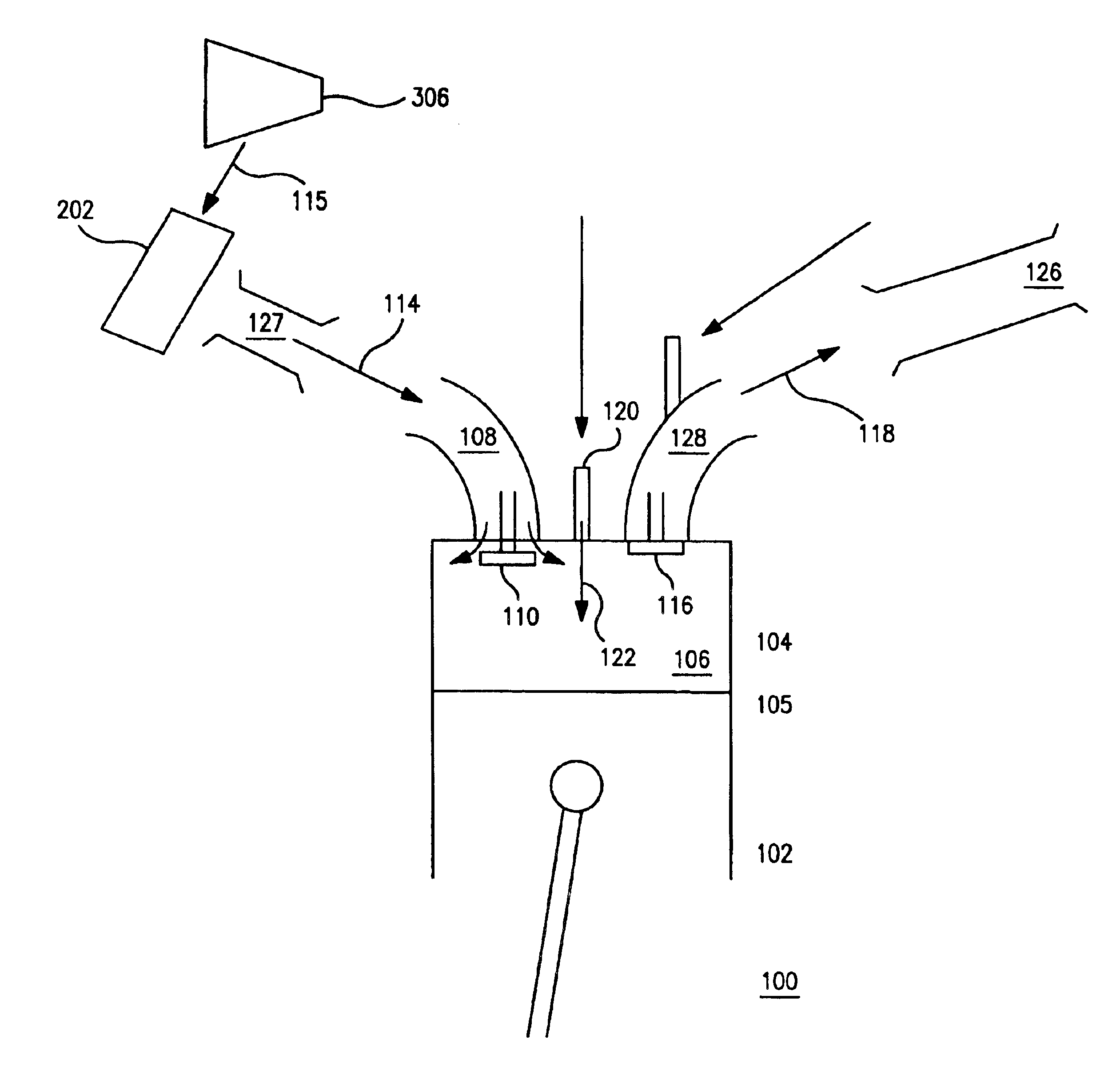
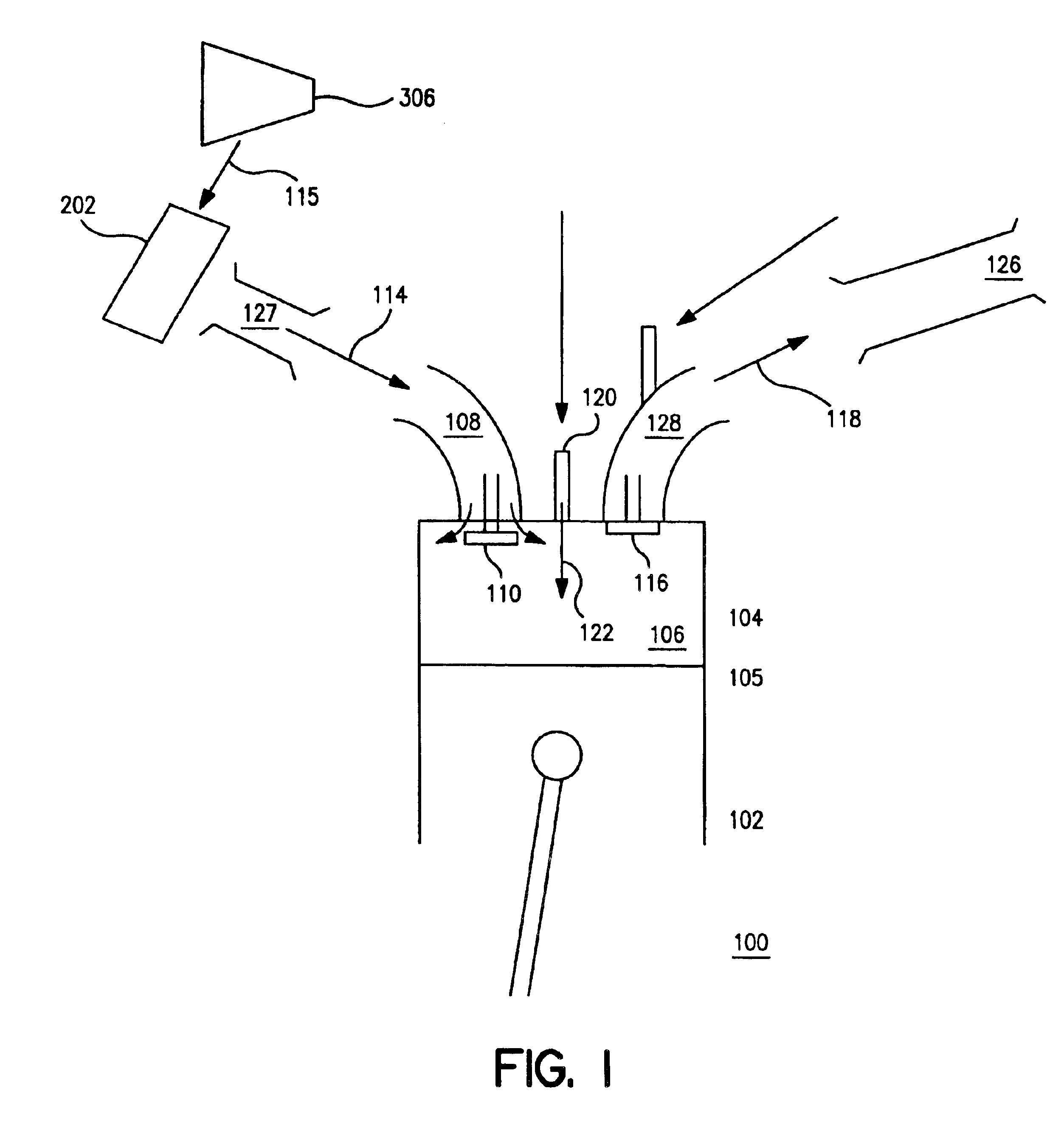
[0043]In FIG. 1 is shown a turbo-charged internal combustion cylinder assembly 100 according to the invention. Although the embodiments described herein are described in the context of a compression-ignited engine, the concept of the invention could be adapted to other types of ignition as well, such as, e.g. spark-, hotbulb- or glowplug-ignited engine.

[0044]In assembly 100 a cylinder 102 has a cylinder head 104 substantially fixedly disposed at one end 105, with a combustion chamber 106 disposed in-cylinder head 104. Cylinder head 104 has an intake port 108 with an intake valve 110 movably disposed in intake port 108, through which combustion chamber 106 may communicate with, e.g. a compressor 306. Compressor 306 may, e.g. provide pre-combustion gases 114 through an intake manifold 127, and also through an aftercooler 202 if so equipped, to combustion chamber 106 when intake valve 110 is substantially open. Pre-combustion gases 114 may be, e.g. air, such as a mixture of nitrogen, o...

second embodiment

[0085]In FIG. 10 is shown a turbo-charged internal combustion engine 1000 according to the invention. In FIG. 10 a plurality of cylinder assemblies 100 may be combined to form an engine 1000. In this embodiment, six cylinder assemblies 100 are combined to form engine 1000. In an alternative embodiment, four cylinder assemblies 100 are combined to form engine 1000. In a further alternative embodiment, eight cylinder assemblies 100 are combined to form engine 1000. Various numbers of cylinder assemblies.100 may be arranged in, e.g. an in-line, a vee, a radial, an opposed, or a flat configuration without departing from the spirit of the invention.

[0086]As shown in FIG. 11, six cylinder assemblies 100 are connected to a first and second turbo-chargers 804, 806. In this embodiment, half of the plurality of cylinder assemblies 100 communicates substantially exclusively via exhaust manifold 126 with first turbo-charger 804, while the other half communicates substantially exclusively via ex...

third embodiment

[0091]In FIG. 12 is shown the invention. In FIG. 12 a turbo-charged internal combustion engine 800 may be installed in a tractor 1200. An embodiment of the invention could also be used in, e.g. stationary applications, marine applications, agricultural equipment, earth moving equipment, locomotives, or aircraft, including lighter-than-air craft.


PUM


Abstract

A turbo-charged internal combustion cylinder assembly includes a combustion chamber which may be communicably connected to a compressor via an intake port through an intake manifold and aftercooler so the compressor may provide pre-combustion gases to the combustion chamber when the intake valve is open. An exhaust port communicably connects the combustion chamber to an exhaust manifold. An exhaust valve may open to exhaust post-combustion gases to the exhaust manifold while an intake valve is substantially closed, and the exhaust valve may open to admit post-combustion gases to the combustion chamber while the intake valve is substantially open and an exhaust port pressure in the exhaust port is higher than a combustion chamber pressure in the combustion chamber. A fuel injector may admit fuel to the combustion chamber. A spill valve may control a rate of fuel injection to the combustion chamber, the spill valve having a first position providing a maximum fuel injection rate, a second position providing a substantially zero fuel injection rate, and at least one intermediate position providing an intermediate fuel injection rate between the maximum fuel injection rate and the zero fuel injection rate.

Description

CROSS-REFERENCE TO RELATED APPLICATIONS[0001]This application is a divisional of U.S. application Ser. No. 10 / 372,929, filed Feb. 26, 2003, now U.S. Pat. No. 6,755,022 which claims the benefit of Provisional Application Ser. No. 60 / 360,005, filed Feb. 28, 2002, the disclosure of which is incorporated by reference.FIELD OF THE INVENTION[0002]The invention relates to internal combustion engines, and in particular, to turbo-charged internal combustion engines with fuel Injection rate shaping and internal exhaust gas recirculation.DESCRIPTION OF THE RELATED ART[0003]Emission control standards for internal combustion engines have tended to become more stringent over time. The sorts of emissions to be controlled tend to fall into at least four broad categories: unburned hydrocarbons, carbon monoxide, particulates, and oxides of nitrogen (NOx). Unburned hydrocarbons and carbon monoxide tend to be produced by inefficient or incomplete combustion. Efficient, complete combustion, on the other...

Claims


Application Information

Patent Timeline
Patent Type & Authority Patents(United States)
IPC IPC(8): B62D49/00F01L1/00F01L5/00F01L5/02F01L7/00F01L9/10F01L9/20F02B1/00F02B1/12F02B27/02F02B29/04F02B33/44F02B37/007F02B37/013F02B37/04F02B37/18F02B39/12F02F1/42F02M25/07F02M45/06F02M45/08F02M57/02F02M59/36
CPCF01L1/00F01L5/00F01L5/02F01L7/00F01L9/02F01L9/04F02B27/04F02B33/44F02B33/446F02B37/04F02B37/18F02B39/12F02M25/0752F02M57/021F02M59/366F01L1/08F01L2800/00F02B1/12F02B29/0406F02M25/0706F02M25/0711Y02T10/121Y02T10/146Y02T10/144F02M26/04F02M26/08F02M26/01Y02T10/12F01L9/10F01L9/20
Inventor KIM, CHARLIE CHANG-WONSUDER, TIMOTHY ANDREWTREVITZ, STEVEN STUARTZSOLDOS, JEFFREY SCOTT
Owner VOLVO LASTVAGNAR AB
Why Eureka
Try Eureka