[0012]The invention defines an equipment control
system consisting of a distributed control
system operating on a real-time network linked to a non-real-time network and at least one control and / or monitoring
station. An operator is able to control the equipment from a master control
station. The master control station and the operator may be located
proximate the equipment, in order to view its operation. “
Proximate” as used herein means that the operator is close enough to, and can make meaningful unaided visual observations of, the equipment in operation so that these visual clues may assist the operator in proper operation of the equipment. For example, if the operator is in a control booth with windows and the operator has an unimpeded view of the equipment, then such operator and the control station are
proximate the equipment. In the alternate configuration, the master control station and the operator may be remotely located. The term “remote” as used herein is the opposite of “proximate”. Remote means distant from the equipment, such that the operator cannot visually observe operation of the equipment without the aid of some optical apparatus such as a
video camera. For example, if the operator's view is obstructed, or the equipment is too distant, or the operator's control booth lacks windows, then the operator and the control station are remote. Furthermore, an operator located onshore will not be able to visually observe the operation on an offshore platform without the aid of a video camera or other optical apparatus, therefore, the operator is considered to be remote. When the operator and the master control station are remotely located, it may be desirable and in some cases indispensable to have one or more video input devices (video cameras) positioned proximate the equipment and one or more electronic displays (video monitors) located near the operator to facilitate observation of the equipment. Sound input devices positioned proximate the equipment may also facilitate monitoring of operations by a remote operator. One or more wellsites may be operated from a single
remote control station.
Split screen technology may be used to reduce the number of electronic displays required. Ancillary control stations may be used to monitor operations. The control stations have the ability to switch functionality, such that an ancillary control station can assume control of the operation and act as the master control station. This gives the control system an added degree of flexibility and safety. This switching is regulated by a safety protocol that ensures that the switching is completed without complications, such as loss of control, and dual control of the equipment.
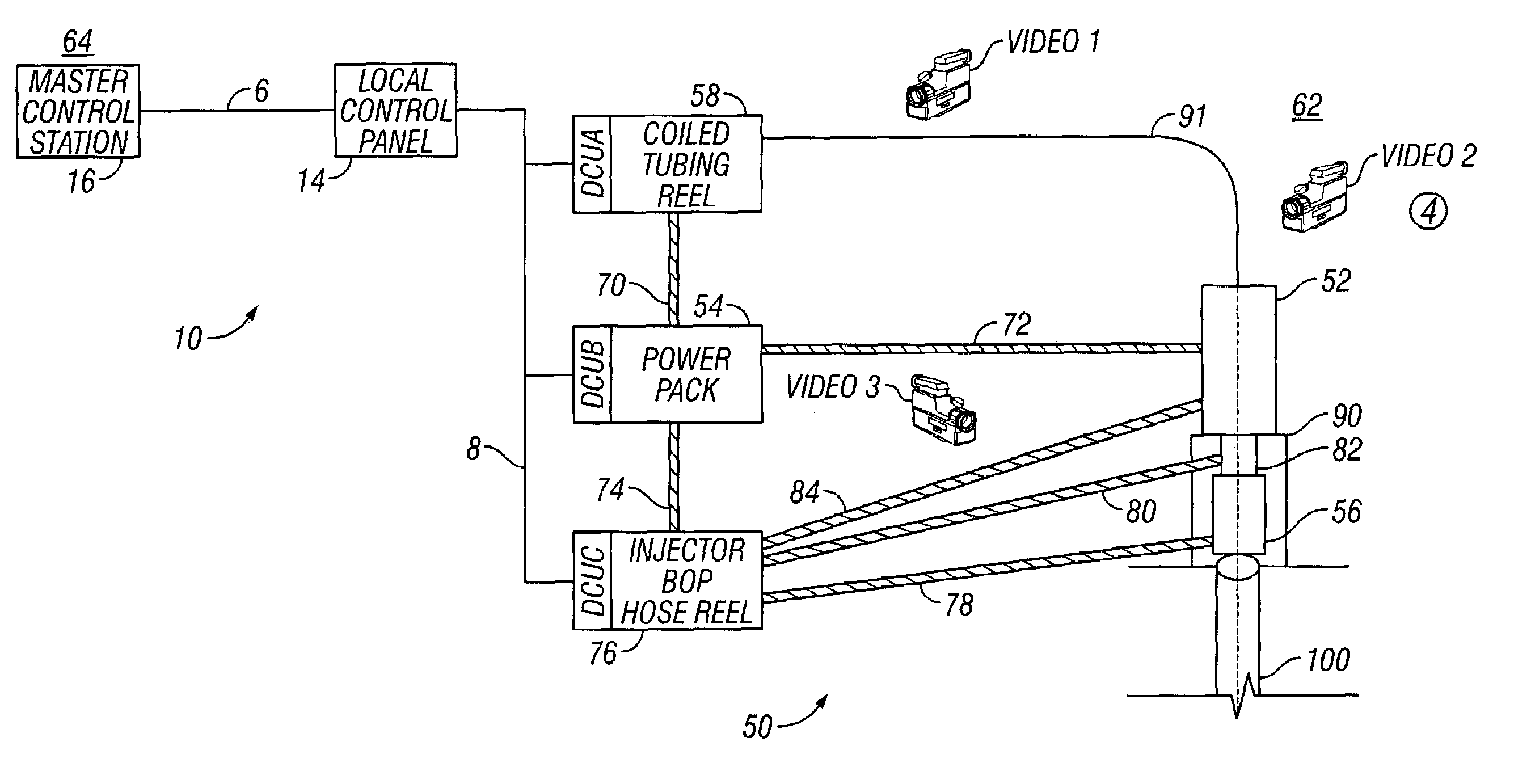
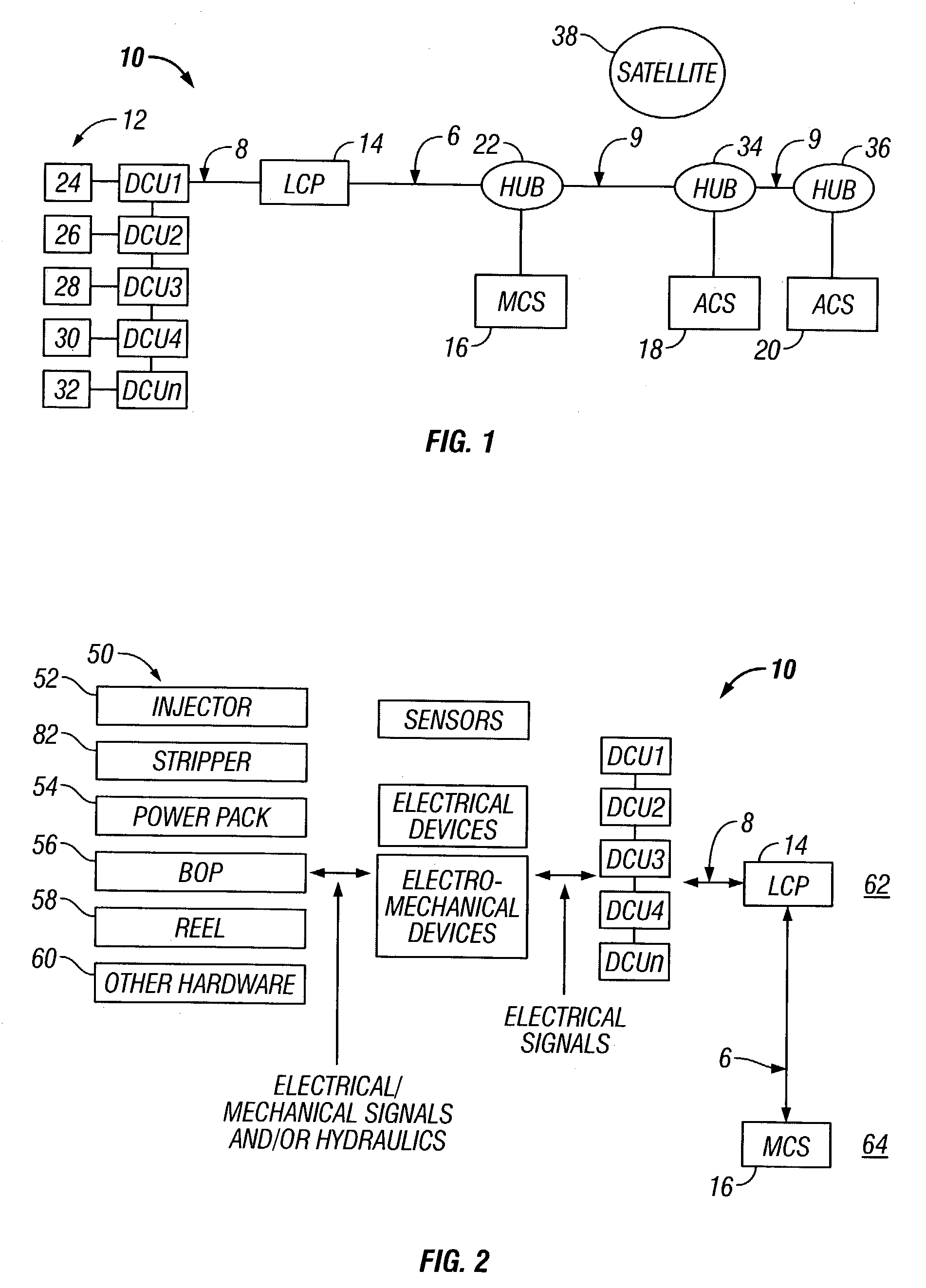
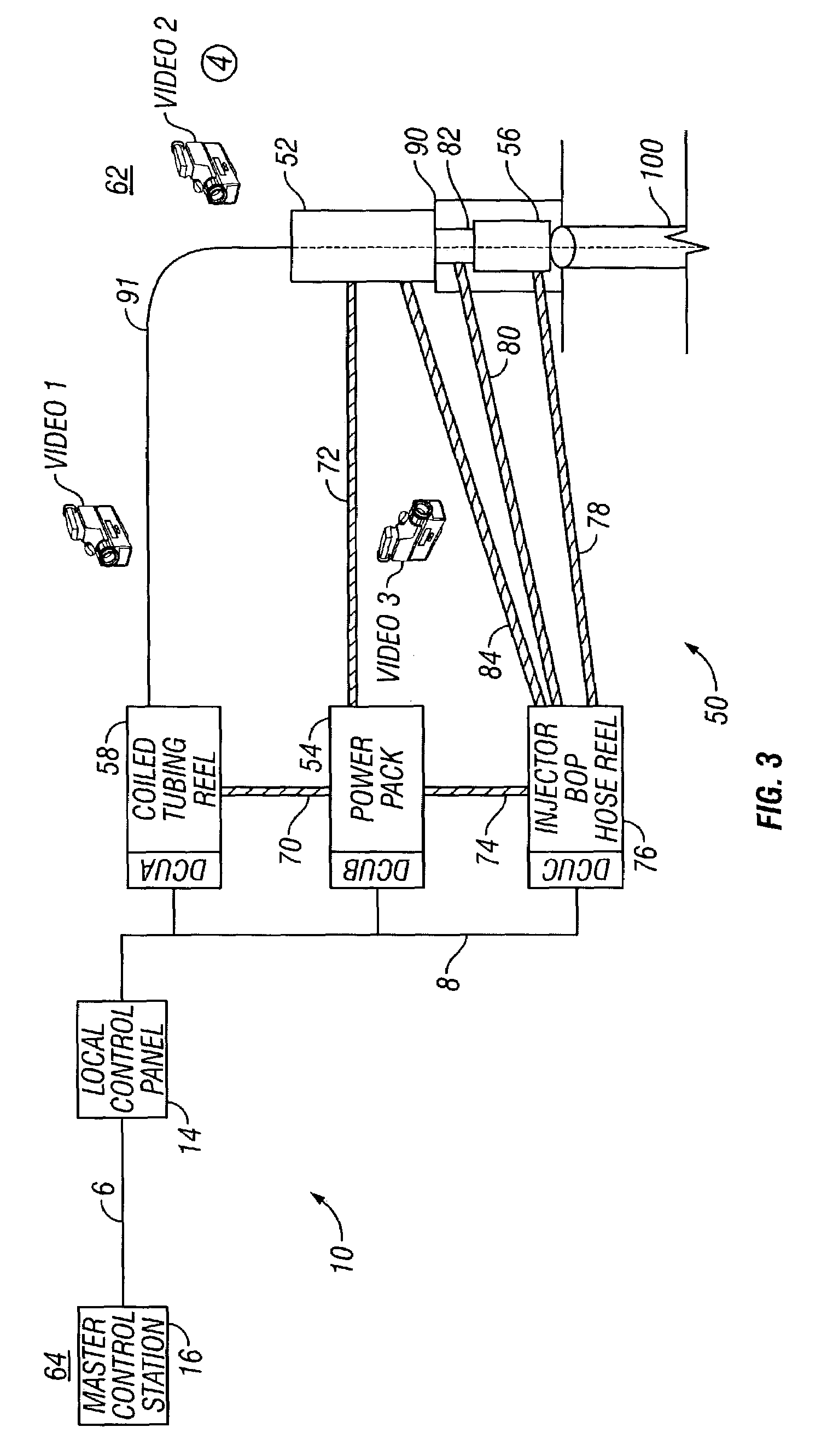
[0013]The master control station is connected to a local control panel (LCP) by an
ETHERNET or other non-real-time network. The LCP is connected to a plurality of distributed control units (DCU) by a controller
area network or other real-time network. Both hard real-time and soft real-time networks are suitable in this invention. However, hard real-time networks are preferred. The LCP provides a bridge between the non-real-time network and the real-time network. The DCU's control various equipment and
mechanical components in the system. The control architecture of the present invention is readily expandable.
[0014]Each DCU and / or the LCP may have control algorithms that provide various levels of control over the equipment. It is preferred that each DCU and / or the LCP have control algorithms that automate the operation of equipment without the intervention of the operator. In this preferred embodiment, each DCU and / or the LCP is programmed to execute a completed task without the intervention of the operator. For example, when a
coiled tubing unit operator issues a command to change the
injector skate pressure from 500 psi (35 kg / square cm) to 1000 psi (70 kg / square cm) or increase the
injector speed from 25 feet / minute (7.6 meters / minute) to 60 feet / minute (18.3 meters / minute), the DCU or LCP performs this task in a controlled manner without additional input from the operator: The DCU and LCP can use open-loop and closed-loop (modifying output based on sensor feedback) control to manipulate the equipment. It is also preferred to program each DCU and / or the LCP to monitor, predict, and automatically control one or a number of critical parameters so that operation limits (also referred to as the operating envelope) will not be exceeded.
[0016]The present invention takes the guesswork out of the operation of a coiled tubing unit. By relying on DCU's and the LCP to automate, monitor, predict, and control operation, the invention increases the safety of the operation and reduces the required
skill level of the operator. Various pre-determined operating parameters or limits, hereinafter referred to as an “operating envelope” may be loaded into the master control station, one or more DCU's, and / or the LCP. A safe operating envelope can be developed based on past experience for a variety of different functions and different situations. The term operating envelope can refer to a single set of operating parameters, multiple sets of parameters, and even calculated values. The present invention reduces the amount of hydraulic hose and the number of connections, which makes it easier and faster to set up and take down. Hose reduction also makes the system more reliable because of fewer leaks. These features make the present invention more economical to operate than prior art units. In a skid mounted coiled tubing unit, the present invention further eliminates the need for a control cabin. This reduces the overall weight of equipment delivered to an offshore platform and saves on equipment cost.

