High dynamic range mass spectrometer

a mass spectrometer and high dynamic range technology, applied in the direction of optical radiation measurement, instruments, separation processes, etc., can solve the problem of not being able to distinguish between single ions being detected, tdc cannot distinguish between different magnitudes, and it is more difficult to obtain accurate quantitative results using a transient recorder

Inactive Publication Date: 2005-11-29
THERMO FINNIGAN
View PDF1 Cites 50 Cited by
  • Summary
  • Abstract
  • Description
  • Claims
  • Application Information

AI Technical Summary

Benefits of technology

[0009]It is an object of the present invention to provide an alternative form of mass spectrometer in which ion counting can be used to cover a wide dynamic range using a small number of TDC's.
[0011]With this arrangement it is possible to measure the quantity of ions with and without attenuation which means that both single and multiple ion detections can be quantified more accurately and a high dynamic range for the mass spectrometer can be achieved. This is achieved by parallel acquisition or interleaved acquisition of signal from ion beams with significant attenuation at one detector element and almost no attenuation at another.
[0014]The detector elements may be disposed one behind the other relative to the ion source or alternatively may be disposed one above the other in a plane extending generally perpendicular to the direction of ion travel. In the case where the detector element is disposed one behind the other, an earthed member preferably a wire or grid may be provided between the elements to minimize capacitative coupling between these elements.

Problems solved by technology

Use of a TDC is generally preferred because it can be more difficult to obtain accurate quantitative results using a transient recorder.
However, a problem arises with a time to digital converter when this is used to count ions in intense ion beams because most TDC's can only detect on event in a finite small time window.
This means that where a TDC is used, it is not normally possible to distinguish between a single ion being detected and a multiplicity of ions being detected at the same time.
This arises because a TDC cannot distinguish between different magnitudes of signal, only whether the detected signal exceeds the predetermined threshold.
Accordingly, a counter connected to the TDC will only be incremented once upon detection of an above threshold signal regardless of its magnitude and therefore in the case of intense ion beams an accurate quantitative measurement cannot be made.
However, the problem with this type of arrangement is that simply spreading the beam over a number of detectors does not affect the intensity of the beam to a sufficient extent to significantly enhance dynamic range without a very large number of TDC's.

Method used


Image

  • High dynamic range mass spectrometer
  • High dynamic range mass spectrometer
  • High dynamic range mass spectrometer

Examples


Embodiment Construction

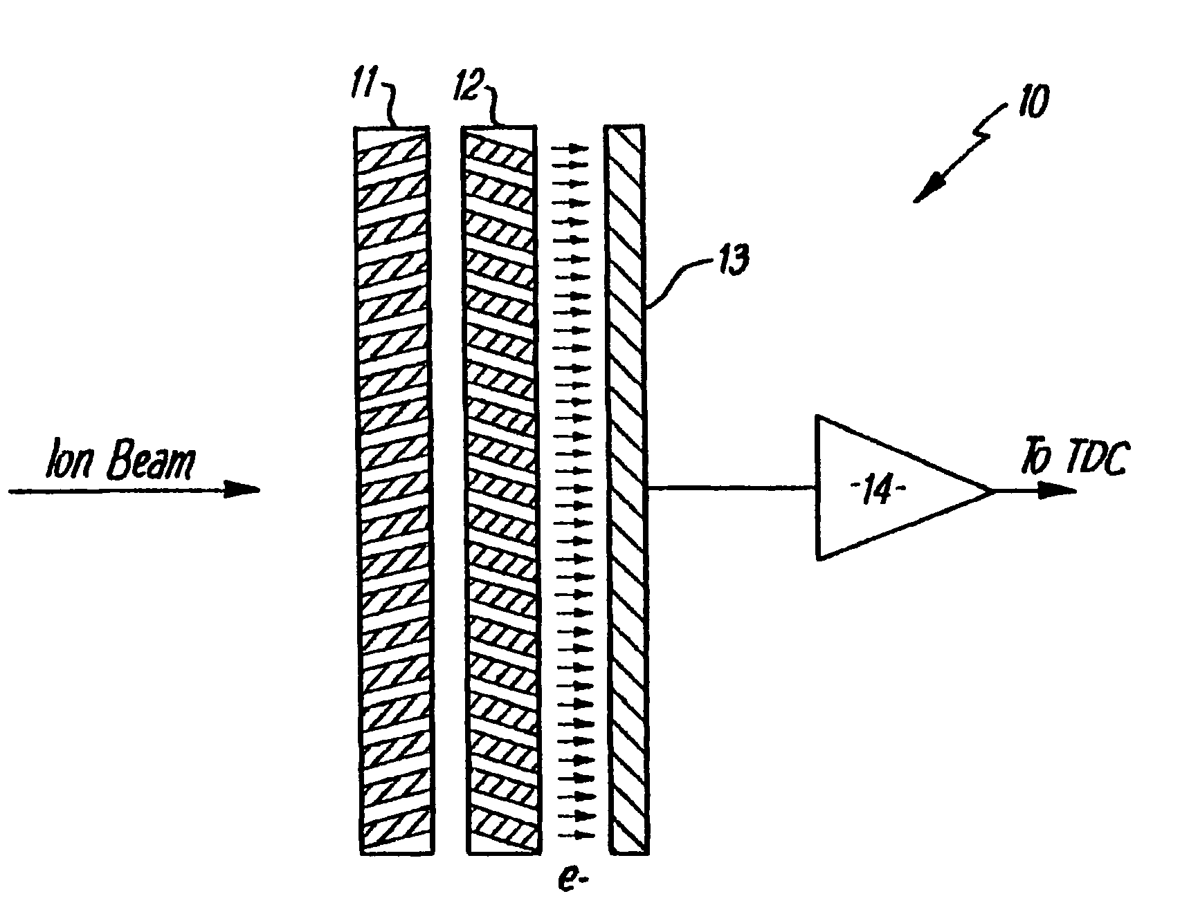
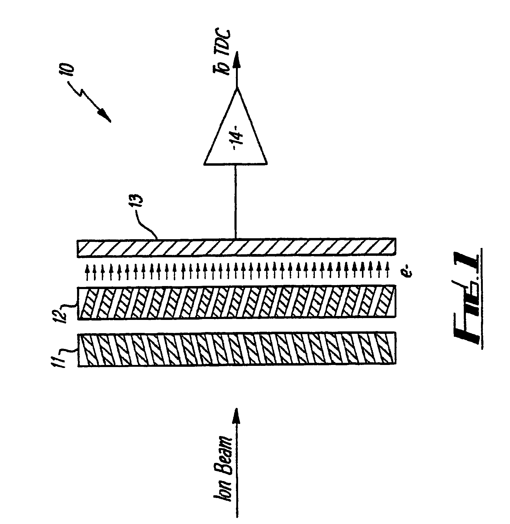
[0025]Referring now to the drawings, there is shown in FIG. 1 a schematic representation of one standard form of prior art mass spectrometer detector. The spectrometer 10 comprises an ion source (not shown) which produces an ion beam from a substance to be analyzed. The ion beam is directed by conventional means onto a pair of microchannel plates 11,12 (hereinafter referred to as a chevron pair) which generates secondary electrons due to the collision of the ions in the ion beam with the material of the plates 11,12 in the microchannels. Secondary electrons generated are detected by a single plate anode 13, the detected signal is amplified in an amplifier 14 and is passed to a time to digital converter (TDC) (not shown) which detects detected signals over a predetermined threshold and increments a counter to count these above threshold signals.

[0026]This form of mass spectrometer suffers from the problem that if an above threshold signal is detected by the TDC, the counter will be i...


PUM

PropertyMeasurementUnit
mass spectrometeraaaaaaaaaa
widthaaaaaaaaaa
massaaaaaaaaaa

Abstract

A mass spectrometer comprises an ion source which produces an ion beam from a substance to be analysed and a detector to detect a quantity of ions incident thereon. The detector includes two elements (16, 18) each of which detect a part of the quantity of ions and an attenuation device attenuates the quantity of ions reaching one of the detector elements. At least one of the detector elements (16, 18) is connected to a time to digital converter (TDC) to allow counting of the ions and at least one of the detector elements is connected in parallel to both a time to digital converter (TDC) and an analogue to digital converter (ADC).

Description

CROSS-REFERENCE TO RELATED APPLICATIONS[0001]This application is a continuation of U.S. patent application Ser. No. 10 / 070,118 filed Aug. 14, 2002 U.S. Pat. No. 6,864,479, entitled “High Dynamic Range Mass Spectrometer,” which is a national stage application under 35 U.S.C. §371 of PCT Application No. PCT / GB00 / 03332, filed Aug. 31, 2000, entitled “High Dynamic Range Mass Spectrometer,” which claims the priority benefit of United Kingdom Patent Application No. 9920711.0, filed Mar. 9, 1999, which applications are incorporated herein by reference in their entireties.BACKGROUND OF THE INVENTION[0002]1. Field of the Invention[0003]This invention relates to a high dynamic range mass spectrometer, preferably although not exclusively of the time of flight kind.[0004]2. Description of the Prior Art[0005]Time of flight (TOF) mass spectrometers are often used for quantitative analysis of substances. In these applications of a TOF mass spectrometer, it will be necessary to be able to accuratel...

Claims


Application Information

Patent Timeline
Patent Type & Authority Patents(United States)
IPC IPC(8): G01N27/62G01Q30/04G01Q60/00H01J49/02H01J49/06H01J49/40
CPCH01J49/025
Inventor DAVIS, STEPHENMAKAROV, ALEXANDER A.HUGHES, JONATHAN
Owner THERMO FINNIGAN
Why Eureka
Try Eureka