Multimedia surveillance and monitoring system including network configuration

a monitoring system and multi-media technology, applied in the field of surveillance and monitoring systems, can solve the problems of affecting the cost of camera and monitor components has steadily fallen, and the limitations of coaxial cable supported systems, so as to improve the security of campus and building, reduce the likelihood of tampering with signals, and be flexible and comprehensive.

Inactive Publication Date: 2005-11-29
PR NEWSWIRE
View PDF6 Cites 1442 Cited by
  • Summary
  • Abstract
  • Description
  • Claims
  • Application Information

AI Technical Summary

Benefits of technology

[0023]The subject invention is a comprehensive multimedia surveillance and monitoring system which is adapted for transmitting event data, video clips, high resolution images, audio signals and other sensor and detector data using digital transmission over both wired, wireless and optical networks. Processors on the networks, private Intranets and the Internet are used for automatic event assessment and response to include the dispatch of response personnel. Geolocation systems are used to locate personnel as well as to indicate the location of one or more events. Automatic mapping, dispatch and response vectoring permit rapid response. Additionally, the system can be used to guide at risk personnel away from harmful events. The wireless components permit local distribution of information with relatively high bandwidth without requirement of a license and without relying on a common carrier and associated fees.
[0063]It is yet another object and feature of the invention to provide vectoring capability for guiding response personnel to specific locations in response to events and for guiding at risk personnel away from such events.

Problems solved by technology

The cost of these systems has come down significantly in recent years as the camera and monitor components have steadily dropped in cost while increasing in quality.
There are several limitations to coaxial cable supported systems.
Long distance video transmission on coaxial cable requires expensive transmission techniques.
Second, both the cable, per se, and the installation is expensive.
Both of these limitations limit practical use of coaxial closed circuit systems to installations requiring less than a few thousand feet of cable.
Third, when the cable cannot be concealed is not only unsightly, but is also subject to tampering and vandalism.
Other hardwired systems have been used, such as fiber optic cable and the like, but have not been widely accepted primarily due to the higher costs associated with such systems over coaxial cable.
This type of system provides an economical link but does not provide transmission over significant distances due to the power constraints placed on the system.
However, the cost is usually much higher per unit, the number of channels is limited and system performance can be greatly affected by building geometry or nearby electrical interference.
Further, the video is not as secure as hardwired systems.
The video may be picked up by anyone having access to the channel while in range of the transmitter and is thus, easily detected and / or jammed.
While commonly available and relatively low in cost, each of these systems is of narrow bandwidth and incapable of carrying “raw” video data such as that produced by a full motion video camera, using rudimentary compression schemes to reduce the amount of data transmitted.
Each of these standards has certain advantages and disadvantages depending upon the volume of data, required resolution and costs targets for the system.
While such devices are useful for their intended purpose, they typically are limited in the amount of data, which may be accumulated and / or transmitted because they do not rely on or have limited compression.
However, such products are limited or difficult, if not impossible, to use for security applications because the resolution and refresh rate (frame rate) of the compressed motion video is necessarily low because of limited resolution of the original sample and the applications of significant levels of video compression to allow use of the low bandwidth circuits.
The low resolution of these images will not allow positive identification of persons at any suitable distance from the camera for example.
The low resolution would not allow the reading of an automobile tag in another example.
As stated, none of the prior art systems readily available accommodates this.
Wide band common carriers such as are used in the broadcast of high quality television signals could be used, but the cost of these long distance microwave, fiber or satellite circuits is prohibitive.

Method used


Image

  • Multimedia surveillance and monitoring system including network configuration
  • Multimedia surveillance and monitoring system including network configuration
  • Multimedia surveillance and monitoring system including network configuration

Examples


Embodiment Construction

Overview

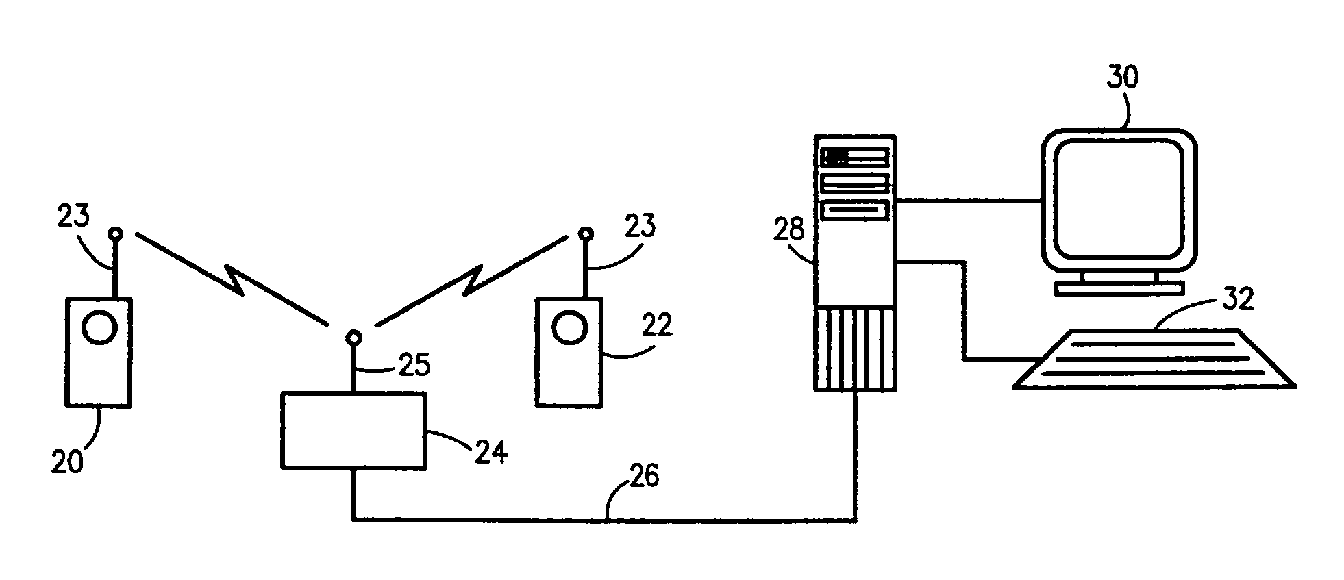
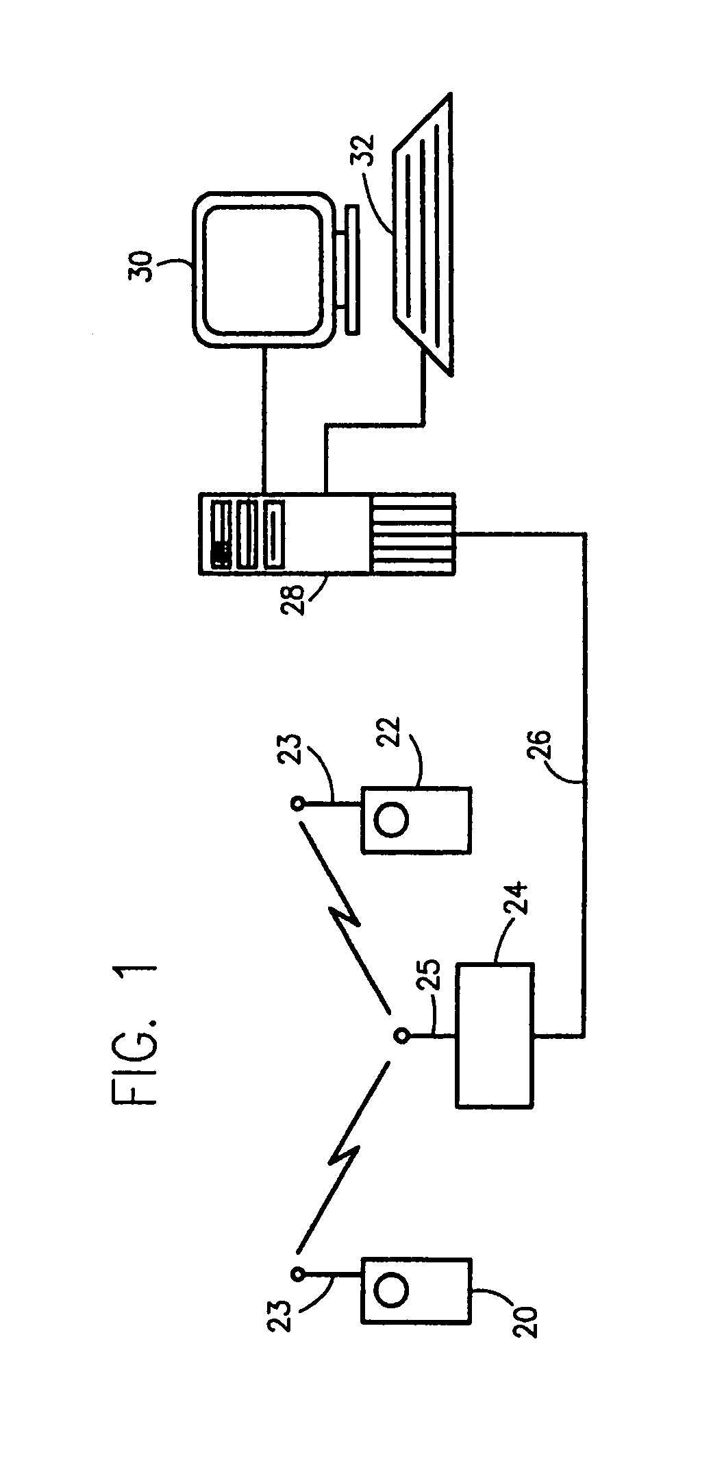
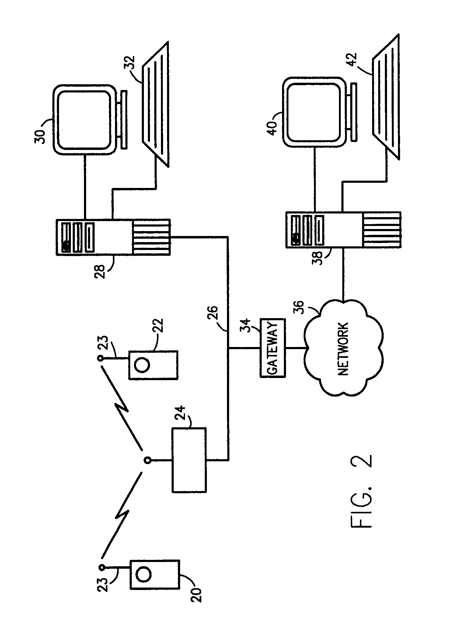
[0173]At the outset, it should be noted that the invention is generally described with all network communication and appliance interconnectivity based on a common protocol, most notably IP protocol, for use in providing communication over a wide area network such as the Internet. The network, at its lowest layer, can be implemented on wire, RF or fiber. In some cases in this application a distinction will be made between wired and wireless circuits. In other cases no distinction is made and the implementation of the LAN or WAN can be based on wire, wireless, or optical circuits. The preferred protocols are PPP or TCP-IP and their derivatives. However, it will be understood that other common protocols may be employed without departing from the scope and spirit of the invention. While this is the preferred communications protocol because of its widespread use and use in conjunction with the Internet, the intent of the invention, as described herein, is to provide the means and...


PUM


Abstract

A comprehensive, wireless multimedia surveillance and monitoring system provides a combination of megapixel digital camera capability with full motion video surveillance with a network, including network components and appliances such as wiring, workstations, and servers with the option of geographical distribution with various wide area carriers. The full service, multi-media surveillance system is capable of a wide range of monitoring techniques utilizing digital network architecture and is adapted for transmitting event data, video and / or image monitoring information, audio signals and other sensor and detector data over significant distances using digital data transmission over a LAN, wireless LAN, Intranet or Internet for automatic assessment and response including dispatch of response personnel. Both wired and wireless appliance and sensor systems may be employed. GPS dispatching is used to locate and alert personnel as well as to indicate the location of an event. Automatic mapping and dispatch permits rapid response. The wireless LAN connectivity permits local distribution of audio, video and image data over a relatively high bandwidth without requirement of a license and without relying on a common carrier and the fees associated therewith. The surveillance system may be interfaced with a WAN (wide area Network) or the Internet for providing a worldwide, low cost surveillance system with virtually unlimited geographic application. Centralized monitoring stations have access to all of the surveillance data from various remote locations via the Internet or the WAN. A server provides a centralized location for data collection, alarm detection and processing, access control, dispatch processing, logging functions and other specialized functions. The server may be inserted virtually anywhere in the Intranet / Internet network. The topology of the network will be established by the geographic situation of the installation. Appropriate firewalls may be set up as desired. The server based system permits a security provider to have access to the appliance and sensor and surveillance data or to configure or reconfigure the system for any station on the network.

Description

BACKGROUND OF THE INVENTION[0001]1. Field of the Invention[0002]The subject invention is directed to surveillance and monitoring systems and is specifically directed to a comprehensive, hybrid multimedia surveillance system based on wireless data transmission, still image and / or step video, video streaming, audio, motion detection, event detection and / or physical condition detection using various network configurations including both wired and wireless Local Area Network (LAN) and Wide Area Network (WAN) communications and network communication techniques and methods with IP compatibility for communication over the Internet.[0003]2. Discussion of the Prior Art[0004]Video monitoring and surveillance of locations or areas for security, safety monitoring, asset protection, process control, and other such applications by use of closed circuit television and similar systems have been in widespread use for many years. The cost of these systems has come down significantly in recent years a...

Claims


Application Information

Patent Timeline
Patent Type & Authority Patents(United States)
IPC IPC(8): G08B5/36G08B7/06G08B25/01G08B25/12H04N7/18
CPCG08B7/062G08B13/19621G08B13/19656G08B13/19658G08B13/19669G08B13/19671G08B13/1968G08B13/19684G08B13/19689G08B13/19691G08B13/19697G08B25/016G08B25/12H04N7/181
Inventor MONROE, DAVID A.
Owner PR NEWSWIRE
Why Eureka
Try Eureka