[0005]In an ESEM, the sample that is to be investigated is placed in an
atmosphere of a gas having a pressure between 0.1
Torr (13 Pa) and 50
Torr (6575 Pa), whereas in a conventional SEM the sample is located in vacuum. The
advantage of an ESEM as compared to a conventional SEM is that the ESEM offers the possibility to form
electron-optical images of moist or non-conducting samples (for example: biological samples, moist samples, plastics,
ceramic materials or glass fibers) which, under the usual vacuum conditions in the conventional SEM, would be difficult to image. The ESEM provides the possibility of maintaining the sample in its
natural state, without having to be subjected to the disadvantageous effects of
drying, freezing or
vacuum coating, which are normally necessary in studies using conventional SEMs.
[0007]The use of a
gaseous atmosphere in an ESEM also makes improved detection means possible. In an ESEM, the liberated
secondary electrons that move in the direction of the secondary
electron detector will collide en
route with gas molecules present in their path. This collision will result in the liberation of new electrons (so called
daughter electrons) from the gas molecules, which will also move in the direction of the secondary
electron detector. In their turn, these newly liberated
daughter electrons will again collide with other gas molecules, etc., so that, as a result of using the gas
atmosphere, an amplification of the secondary electron
signal occurs. It will be apparent that, the greater the distance that the
secondary electrons have to travel to the secondary electron detector, the greater the number of collisions that will occur between secondary electrons and gas molecules. In this
scenario, one should make allowances for the fact that the dimensions of the
sample chamber or detection space of the
electron microscope are preferably such that the length of the path that the primary beam must
traverse through the pressurized
sample chamber is as small as possible. This is because the gas molecules present also cause scattering of the primary beam, seeing as electrons from the primary beam can collide with the gas molecules.
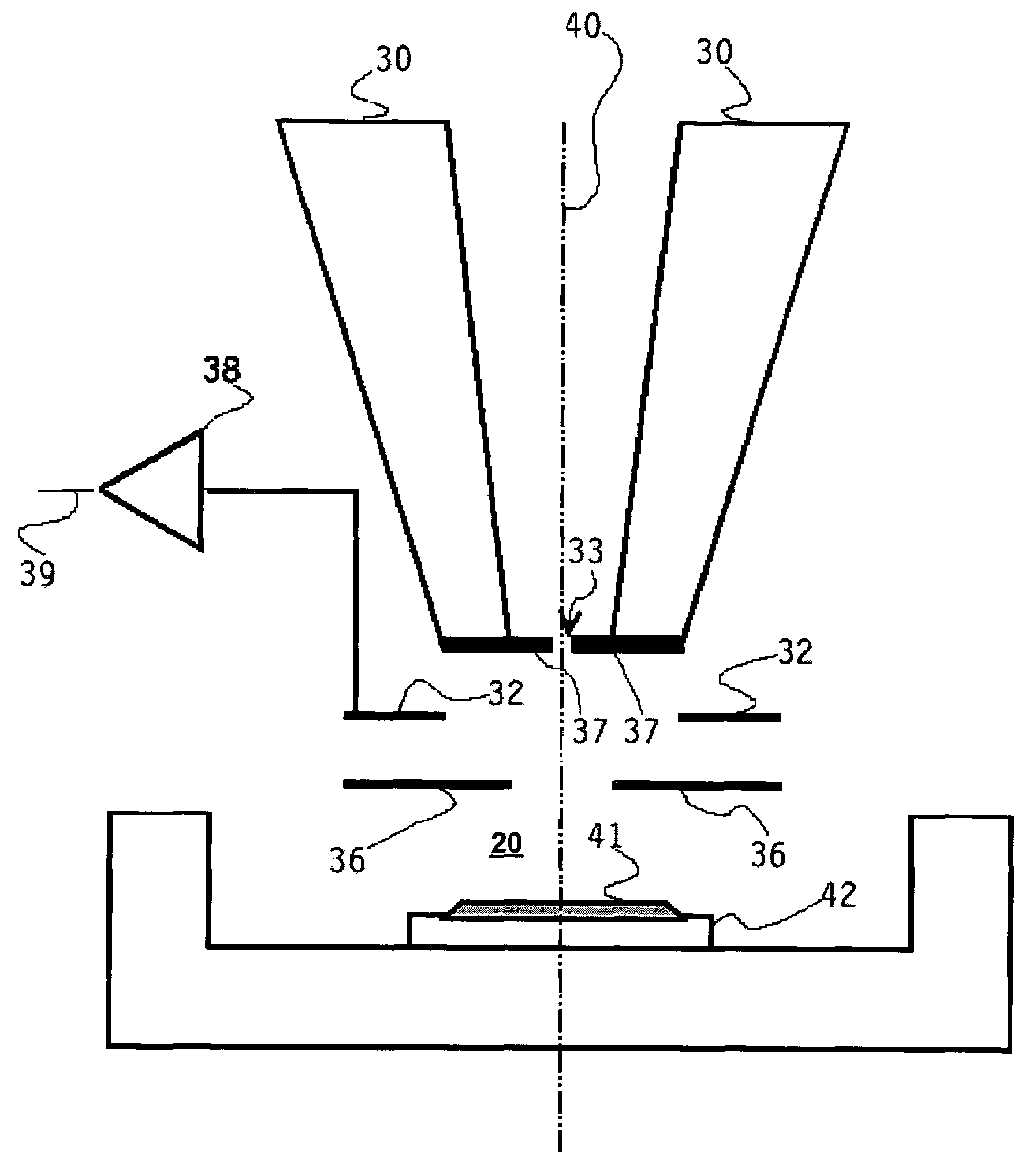
[0008]In the cited abstract number 5-174768, an ESEM is disclosed wherein the primary beam from the
particle source is focused on the sample by means of an immersion lens. The immersion lens consists of a
magnetic dipole whose poles are located on opposite sides of the
sample chamber formed by the sample holder and primary
beam source. In this manner, a magnetic field is present in the sample chamber. The secondary electrons liberated from the sample will be influenced by the magnetic field while on their way to the detector, as a result of which they will follow a
helical path. It is claimed that in this way, the distance traversed by the secondary electrons is greatly increased, so that the
collision probability proportionately increases and the
amplification factor of the detection apparatus increases. A
disadvantage of the disclosed device described here above is that, in the given configuration, the electrons follow a
helical path around an axis that extends parallel to a magnetic field. The distance traversed by the electron from the sample to the detector is directly dependent upon the distance between the detector and the sample in the direction of the magnetic field. In the illustrated case, this means that the detector
electrode should be located as high as possible above the sample, so as to achieve as large an
amplification factor as possible. Attendant upon this is the fact that the distance traversed by the primary beam through the sample chamber (and thus through the
gaseous atmosphere) shall also be large. As a result of this, scattering of the primary beam will increase. An increased
amplification factor for the detection apparatus is thus achieved at the expense of the resolving power of the illustrated device.SUMMARY OF THE INVENTION
[0009]It is therefore an object of the present invention to provide a particle-optical device in which the working distance (the distance traversed by the primary beam through the detection space) is as small as possible, but the amplification factor of the detection means is as large as possible. It is to be understood that detection includes direct collection of charged particles and induction of
signal in an
external circuit caused by the movement of charged particles.
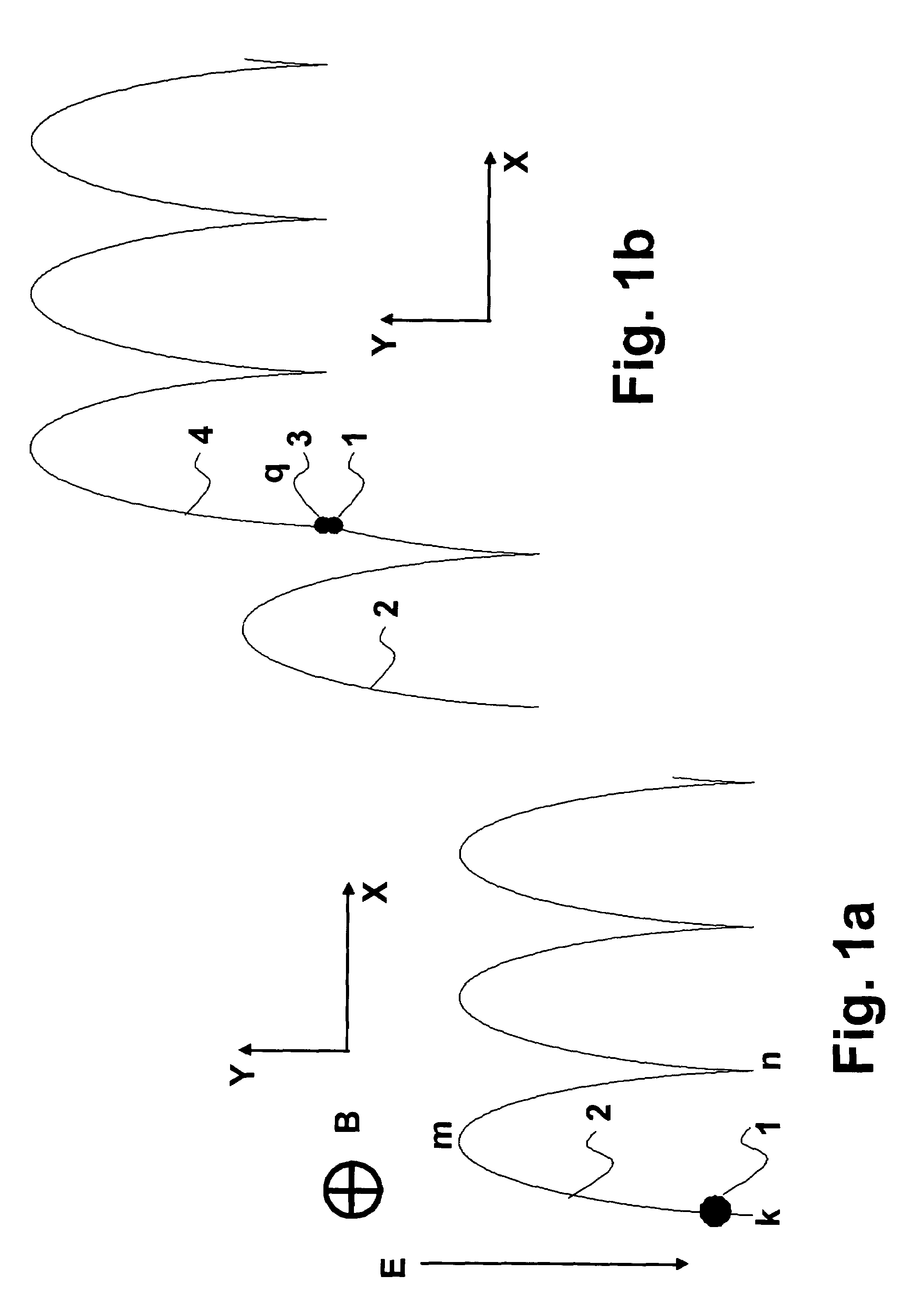
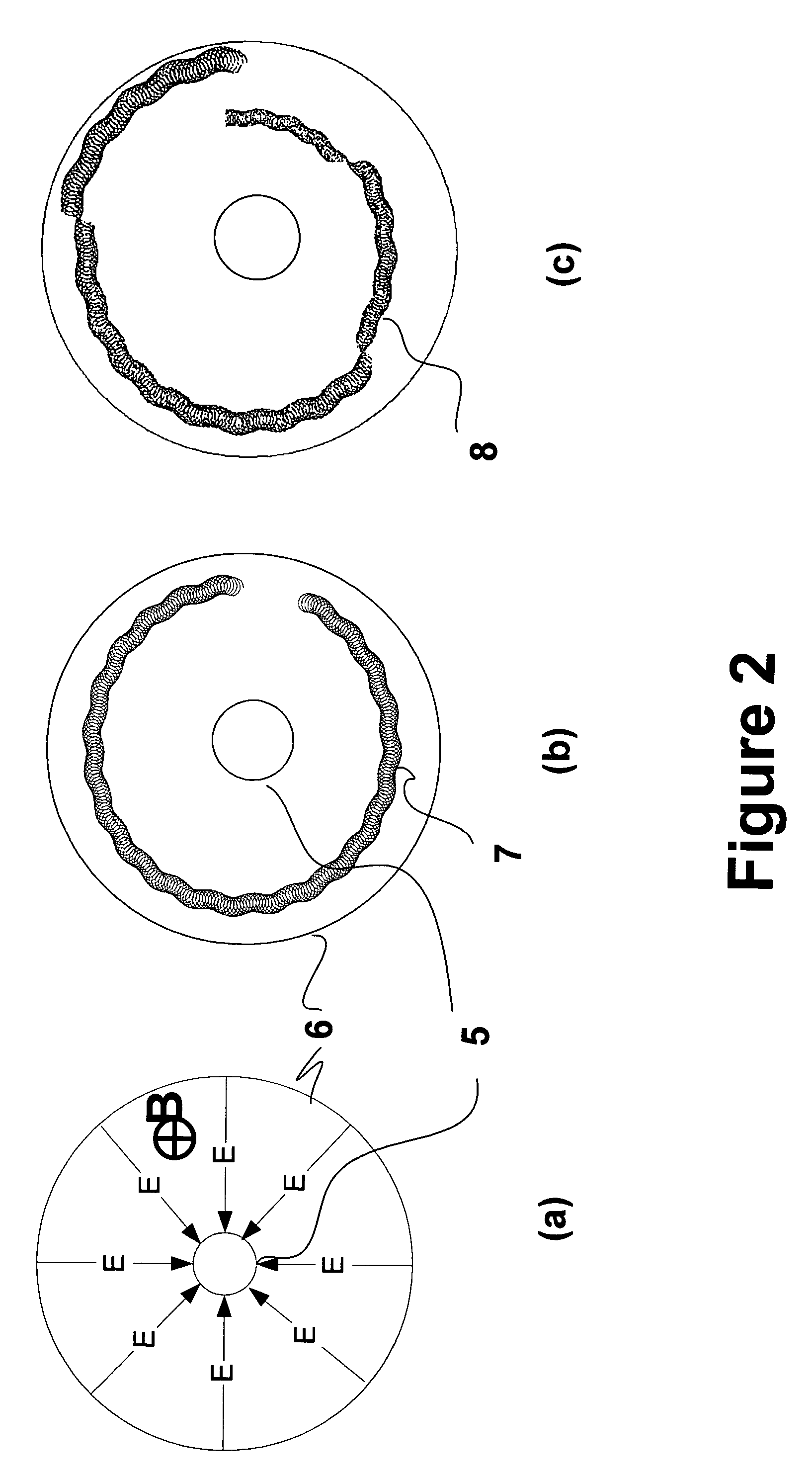
[0010]These and other objects have been achieved in the present invention in that said first detection means and said immersion lens are arranged for providing the
electric field and the magnetic field such that the detection space comprises a first portion in which the electric field is oriented transverse to the magnetic field. It can be shown that the motion of the low energy electrons in this field structure can create a large amplification factor, provided that certain values of electric field and magnetic field are present. It can further be shown that this large amplification can take place even with a low pressure of gas, which further reduces the scattering of the primary beam.

