Injection locking type or MOPA type of gas laser device

a laser device and locking type technology, applied in the direction of instruments, photomechanical devices, active medium materials, etc., can solve the problems achieve the effect of reducing the installation area of the laser device, minimizing the evacuation distance, and small for

Inactive Publication Date: 2005-12-06
GIGAPHOTON
View PDF23 Cites 18 Cited by
  • Summary
  • Abstract
  • Description
  • Claims
  • Application Information

AI Technical Summary

Benefits of technology

[0009]A second constitution of the injection locking type or MOPA type of gas laser device according to the present invention includes: a seed laser unit for exciting a laser gas inside a laser chamber and oscillating seed laser light; and an amplifier for exciting a laser gas inside an amplifying chamber and amplifying pulse energy of the seed laser light; and allows the laser chamber and the amplifying chamber to be evacuated to the same side with respect to an optical axis of the seed laser light. Accordingly, it becomes possible to draw out the chambers to the same side and perform maintenance, whereby it becomes unnecessary to provide a space for maintenance on both sides of each of the chambers, thereby reducing the installation area of the laser device.
[0010]The gas laser device may further include: rails for mounting the laser chamber and the amplifying chamber thereon respectively; in which the laser chamber and the amplifying chamber may be evacuated along the rails. Hence, when being evacuated, the chambers can be evacuated along the rails, whereby there is a low possibility of the chambers shaking and thereby hitting the optical components and the like.
[0011]In the gas laser device, the laser chamber and the amplifying chamber may be respectively mounted on the rails via rotatable rollers. Therefore, the evacuation of chambers can be performed with small force. Further, in the gas laser device, the rails may be placed almost perpendicularly to the optical axis of the seed laser light. Hence, it becomes possible to minimize the evacuation distance of each of the chambers and locate the chambers farther away from the seed laser light. Furthermore, in the gas laser device, the laser chamber and the amplifying chamber may be mounted on the same rails. Consequently, a space required to provide the rails is reduced.
[0012]Besides, in the gas laser device, the laser chamber and the amplifying chamber may be arranged vertically to each other, whereby the installation area of the laser device can be reduced. In addition, in the gas laser device, at least one of the laser chamber and the amplifying chamber may be placed so that the emitted laser light is oriented in a vertical direction. As a result, when a power source is removed from the chamber, it is unnecessary to lift the heavy power source, and the power source can be moved in a horizontal direction from the path of the chamber, whereby its movement is facilitated.
[0013]Moreover, the laser device may further include: an optical path cover for covering an optical path space which the seed laser light passes through; and a purge mechanism for filling the interior of the optical path space with a clean purge gas with low reactivity. Thereby, even if the seed laser light has vacuum ultraviolet wavelength, the seed laser light is never attenuated by the mixing of oxygen into the optical path space. In addition, impurities such as dust in the optical path space seldom adhere into the optical components. Further, the gas laser device may further include optical axis adjusting means for adjusting the optical axis of the seed laser light. Accordingly, the seed laser light can be suitably introduced into the amplifier, whereby pulse energy of the amplified laser light emitted from the amplifier can be increased.
[0014]Furthermore, in the gas laser device, the optical axis adjusting means may be an optical path mirror for reflecting the seed laser light. Consequently, the optical axis can be adjusted easily by adjusting the optical path mirror. Moreover, the gas laser device may further include: manipulating means for manipulating an angle of the optical path mirror from outside the optical path space; and sealing means for preventing outside air from being mixed into the optical path space when the manipulating means is manipulated. Accordingly, even if the optical path mirror is manipulated, neither oxygen nor dust is mixed into the optical path space, whereby attenuation of the seed laser light and adhesion of dust to the optical mirror and so on seldom occur. Further, in the gas laser device, the optical axis adjusting means may be moving means for moving cavity plates for fixing a resonator of the laser chamber. Hence, the laser chamber and the amplifying chamber can be arranged in a straight line, whereby the installation area of the laser device can be reduced.

Problems solved by technology

Accordingly, it becomes unnecessary to provide a space for maintenance on both sides of each of the chambers, thereby reducing the installation area of the laser device.

Method used


Image

  • Injection locking type or MOPA type of gas laser device
  • Injection locking type or MOPA type of gas laser device
  • Injection locking type or MOPA type of gas laser device

Examples


first embodiment

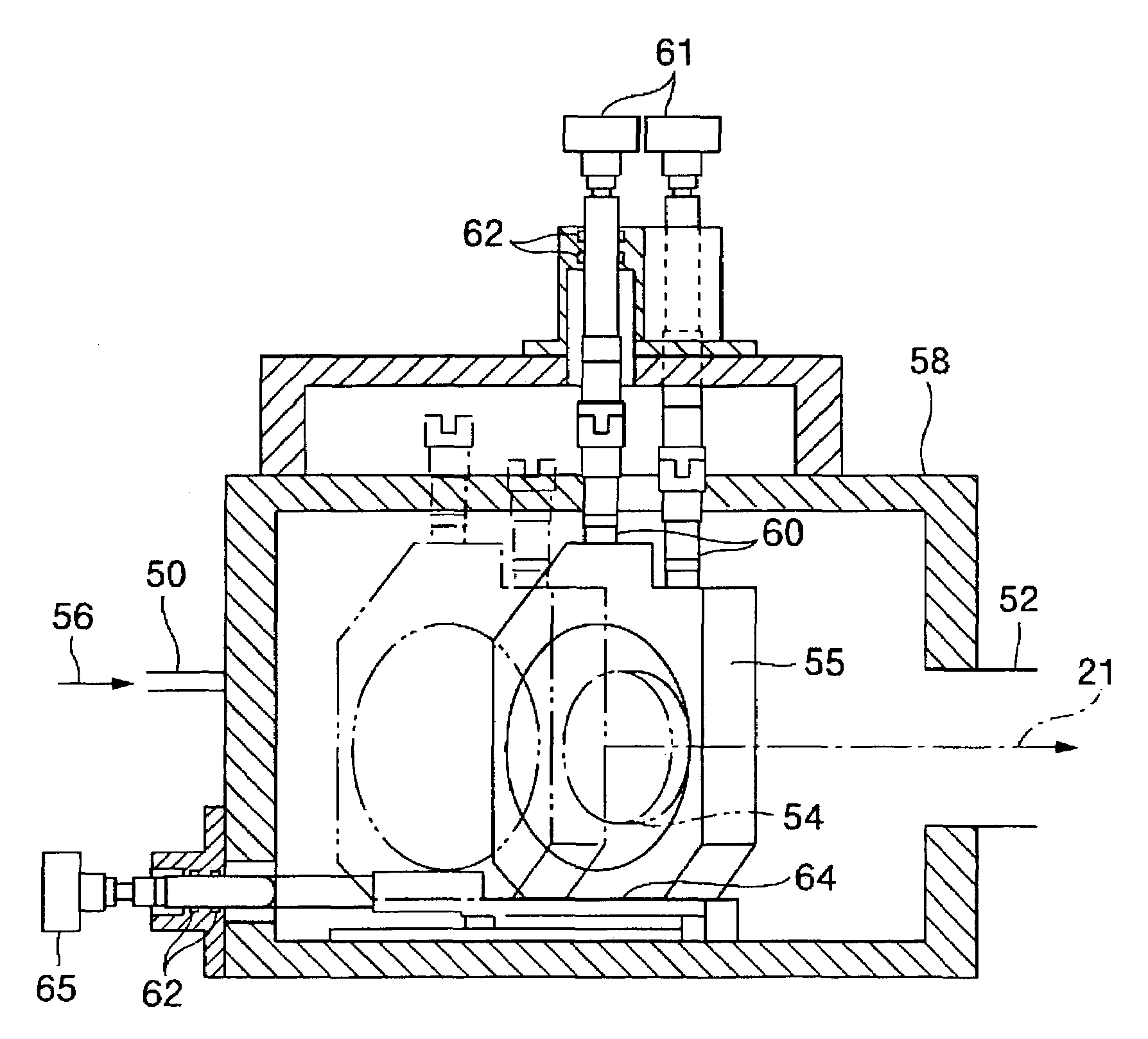
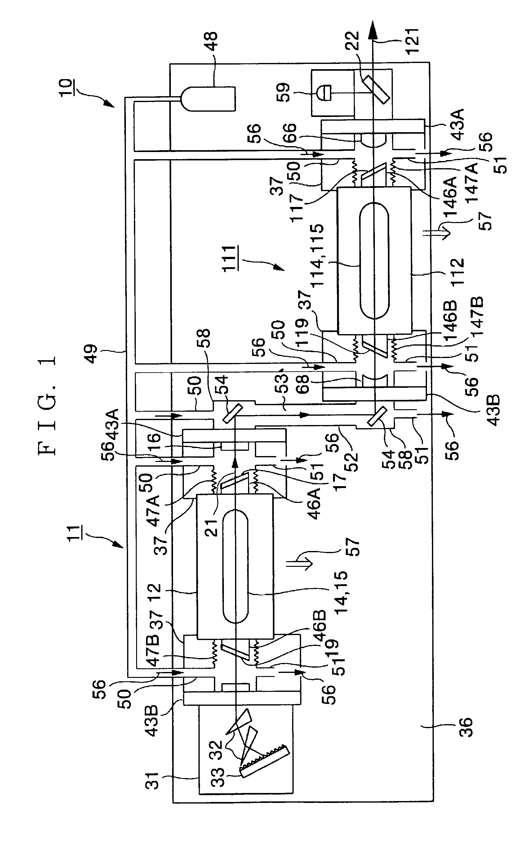
[0033]First, a first embodiment will be explained. FIG. 1 shows a block diagram of an injection locking type of fluorine molecular laser device 10 (hereinafter referred to as the laser device 10) in plan view. In FIG. 1, the laser device 10 includes a seed laser unit 11 for oscillating band-narrowed seed laser light 21 and an amplifier 111 for amplifying the seed laser light 21 while keeping its wavelength and spectrum line width. The seed laser unit 11 and the amplifier 111 are mounted on a base plate 36, for example, made of cast iron.

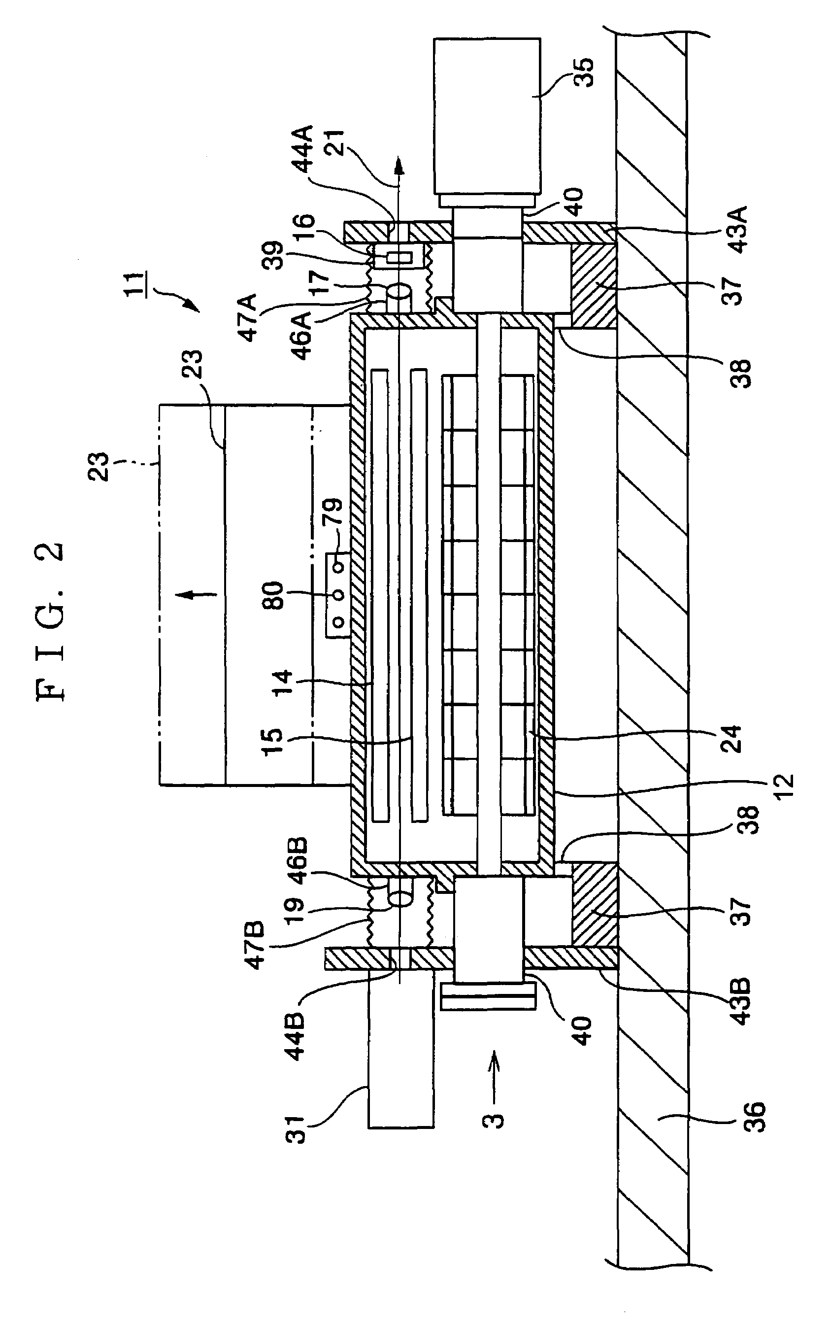
[0034]FIG. 2 shows a front view of the seed laser unit 11. As shown in FIG. 2, the seed laser unit 11 includes a laser chamber 12 which seals in a laser gas containing fluorine. Two left and light rails 37 and 37 are fixed on the top of the base plate 36 almost perpendicularly to their longitudinal direction (left-right direction in FIG. 1). For example, four rollers (wheels) 38 and 38 are rotatably fixed to the bottom of the laser chamber 12. The ro...

fifth embodiment

[0059]FIG. 12 shows a front view of the laser device 10 according to a In FIG. 12, the rails 37 and 37 are fixed onto the upper base plate 36A perpendicularly to the paper surface in FIG. 12, and the laser chamber 12 is mounted on the rails 37 and 37 via the rollers 38 so that the optical axis of the emitted seed laser light 21 substantially coincides with a vertical direction. The laser chamber 12 includes a cavity frame 78 obtained by integrating two cavity plate 43A and cavity plate 43B and a bridge connecting them to take the shape of U tilted by 90 degrees. Similarly to the aforementioned respective embodiments, optical components such as the band-narrowing box 31 are fixed to the cavity plates 43A and 43B.

[0060]The cavity frame 78 is movable by cavity rollers 81 and positioned by positioning bolts 82 and 82. The seed laser light 21 emitted downward from the seed laser unit 11 is reflected by the optical path mirror 54 and incident on the amplifier 111. The high voltage power ...


PUM


Abstract

An injection locking type or MOPA type of gas laser device which requires only a small installation area and allows easy maintenance. For this purpose, the laser device includes a seed laser unit (11) for exciting a laser gas inside a laser chamber (12) and oscillating seed laser light (21) and an amplifier (111) for exciting a laser gas inside an amplifying chamber (112) and amplifying pulse energy of the seed laser light (21), and allows the laser chamber (12) and the amplifying chamber (112) to be evacuated to the same side with respect to an optical axis of the seed laser light (21).

Description

TECHNICAL FIELD[0001]The present invention relates to an injection locking type or MOPA type of gas laser device.BACKGROUND ART[0002]An injection locking type or MOPA (Main Oscillator Power Amplifier) type of laser device in which seed laser light oscillated from a seed laser unit is amplified by an amplifier is conventionally known. FIG. 17 represents an MOPA type of fluorine molecular laser device 90 (hereinafter referred to as the laser device 90) shown in “Feasibility of Highly Line-Narrowed F2 laser for 157 nm Microlithography (2000 SPIE Cymer, Inc)”, and a prior art will be explained below based on FIG. 17.[0003]In FIG. 17, the laser device 90 includes a seed laser unit 11 for oscillating seed laser light 21 and an amplifier 111 for amplifying the seed laser light 21. The seed laser unit 11 and the amplifier 111 include a laser chamber 12 and an amplifying chamber 112 for sealing in a laser gas respectively. The spectral line width of the seed laser light 21 generated by disch...

Claims


Application Information

Patent Timeline
Patent Type & Authority Patents(United States)
IPC IPC(8): H01S3/02H01S3/0971H01S3/03H01S3/034H01S3/08H01S3/225H01S3/23
CPCG03F7/70975H01S3/225H01S3/2366H01S3/025H01S3/03H01S3/034H01S3/08009H01S3/2258H01S3/2308
Inventor YAMASHITA, TOSHIOWAKABAYASHI, OSAMU
Owner GIGAPHOTON
Why Eureka
Try Eureka