Method of chemical decontamination and system therefor
a chemical decontamination and chemical technology, applied in nuclear fuel elements, radioactive decontamination, nuclear power plants, etc., can solve problems such as increasing system costs, and achieve the effect of increasing system costs and moderate material corrosion
- Summary
- Abstract
- Description
- Claims
- Application Information
AI Technical Summary
Benefits of technology
Problems solved by technology
Method used
Image
Examples
embodiment 1
[Embodiment 1]
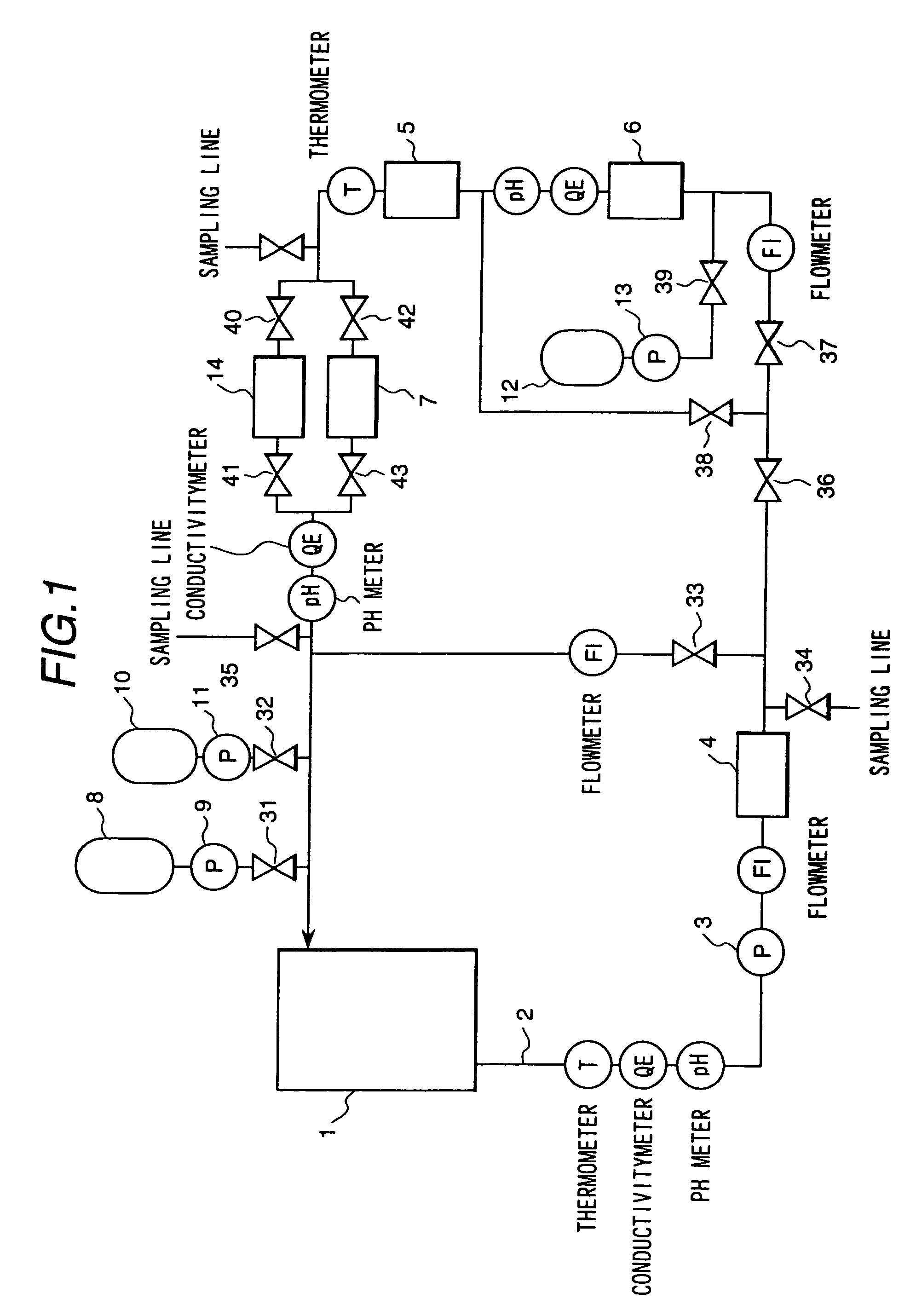
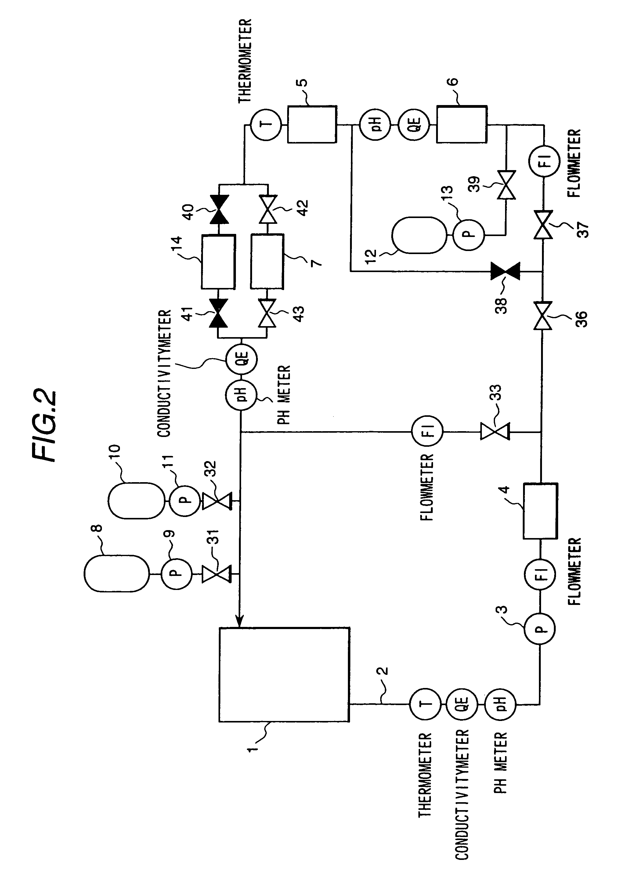
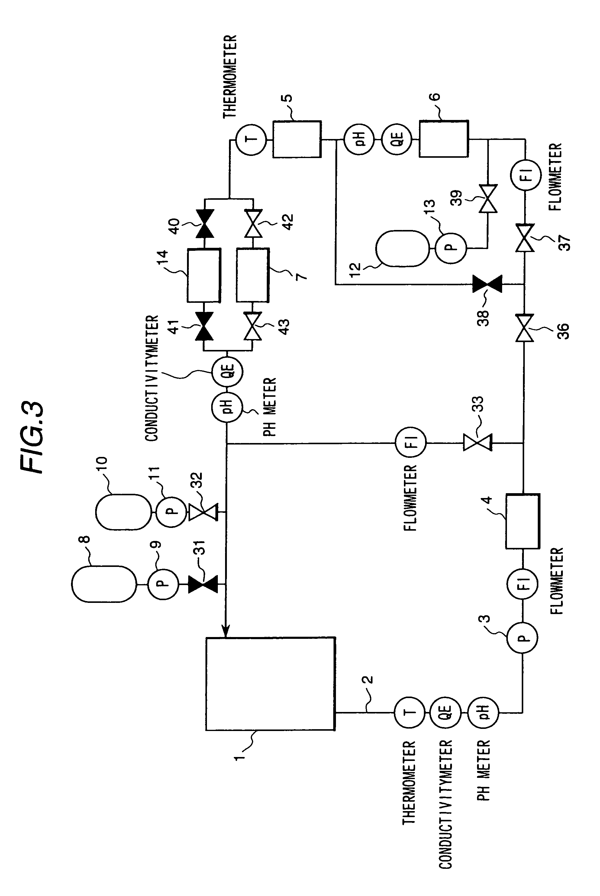
[0033]FIG. 1 is a diagram showing the basic system configuration of a chemical decontamination system to which an embodiment of a chemical decontamination method in accordance with the present invention is applied. Components used for performing decontamination are a circulation line 2 connected to a portion 1 to be decontaminated (pipes of a nuclear power plant and so on), a circulation pump 3, a heater 4, a cooler 5, a catalyst decomposition column 6, a cation resin column 7, an agent tank 8, an agent injection pump 9, a pH adjusting agent tank 10, a pH adjusting agent injecting pump 11, a hydrogen peroxide tank 12, a hydrogen peroxide injection pump 13 and a mixed-bed resin column 14. Each of the above-described components and each valve to be described later are connected with a piping path.
[0034]FIG. 7(A) shows a main process of the present embodiment of a chemical decontamination method. The reducing treatment shown in FIG. 7 indicates decontamination using a red...
embodiment 2
[Embodiment 2]
[0057]Although in Embodiment 1 the vent mechanism is arranged in the catalyst decomposition column 6 in order to remove the produced gas, a gas-liquid separating tank having a vent cooler for separating the gas may be arranged downstream of the catalyst decomposition column 6 and upstream of the cation resin column 7. In this case, there is an advantage in that the gas-liquid separating tank 13 can also be used as a buffer for receiving a volume of liquid increased by injection of the agent.
embodiment 3
[Embodiment 3]
[0058]FIG. 9 is a diagram showing the basic system configuration of a chemical decontamination system to which a third embodiment of a chemical decontamination method in accordance with the present invention is applied.
[0059]The main process in the present embodiment of the chemical decontamination method is shown in FIG. 7(B). A different point of Embodiment 3 from Embodiment 1 (system configuration of FIG. 1) is that the position of the catalyst decomposition column 6 and the position of the cation resin column 7, the mixed-bed resin column 14 and the cooler 5 are in inverse order.
[0060]In Embodiment 3, the cooler 5, the cation resin column 7 and the mixed-bed resin column 14 are arranged in the upstream side of the catalyst decomposition column 6.
[0061]An advantage of the system configuration shown in Embodiment 3 is that the concentration of radioactivity in the water flowing to the catalyst decomposition column 6 is low because the water flows into the catalyst de...
PUM
 Abstract
Description
Claims
Application Information
 - R&D
- Intellectual Property
- Life Sciences
- Materials
- Tech Scout
- Unparalleled Data Quality
- Higher Quality Content
- 60% Fewer Hallucinations
Browse by: Latest US Patents, China's latest patents, Technical Efficacy Thesaurus, Application Domain, Technology Topic, Popular Technical Reports.
© 2025 PatSnap. All rights reserved.Legal|Privacy policy|Modern Slavery Act Transparency Statement|Sitemap|About US| Contact US: help@patsnap.com


