
Method and apparatus for measuring pressure of a fluid medium and applications thereof

a fluid medium and pressure measurement technology, applied in the direction of fluid pressure measurement by electric/magnetic elements, measuring devices, instruments, etc., can solve the problems of filament immediately burning up, cumbersome and high cost, large dimensions, etc., and achieve the effect of simple, inexpensive and efficient, and infinite li

Inactive Publication Date: 2005-12-13
A T C T ADVANCED THERMAL CHIP TECH
View PDF5 Cites 14 Cited by
  • Summary
  • Abstract
  • Description
  • Claims
  • Application Information

AI Technical Summary

Benefits of technology

[0009]In this respect, references is made to U.S. Pat. No. 6,509,553, assigned to the same assignee as the present application, disclosing the use of positive temperature coefficient thermistors for providing an indication of the composition of a fluid medium in which the thermistor is immersed. Reference is also made to U.S. patent application Ser. No. 10 / 344,134, filed Aug. 16, 2001, also assigned to the same assignee as the present application, disclosing the use of positive temperature coefficient thermistors for efficiently evaporating liquids, such as for the removal of water condensation in air conditioning systems. Further, reference is made to U.S. patent application Ser. No. 10 / 844,397 filed May 13, 2004, disclosing the use of positive temperature coefficient thermistors for measuring flow velocity, including measuring heat flow, wind velocity, and wind direction. The present invention relates to yet additional applications of PTC thermistors involving the measurement of fluid medium pressure.
[0015]As will be described more particularly below, such method and apparatus can be implemented in relatively simple, inexpensive and efficient systems for making various measurements involving the measurement of fluid medium pressure as briefly mentioned above. Particular advantages of the invention, especially when implemented in those applications as to be described more particularly below, are that the apparatus requires substantially no moving parts, substantially no maintenance, has a virtually infinite lifetime, and / or may be used in applications involving a wide range of pressure measurements.

Problems solved by technology

However, such gauges require temperatures of over 1,000° C., and generally are of large dimensions, cumbersome and of high cost.
Also, if this gauge is accidentally exposed to atmospheric environment, the filament is immediately burnt up due to its high temperature.
Moreover, because of the extremely large range of pressures that may be involved in a vacuum system, from atmospheric down to 10−12 bar or less, there is no single vacuum gauge which covers the whole range.

Method used


Image

  • Method and apparatus for measuring pressure of a fluid medium and applications thereof
  • Method and apparatus for measuring pressure of a fluid medium and applications thereof
  • Method and apparatus for measuring pressure of a fluid medium and applications thereof

Examples


Embodiment Construction

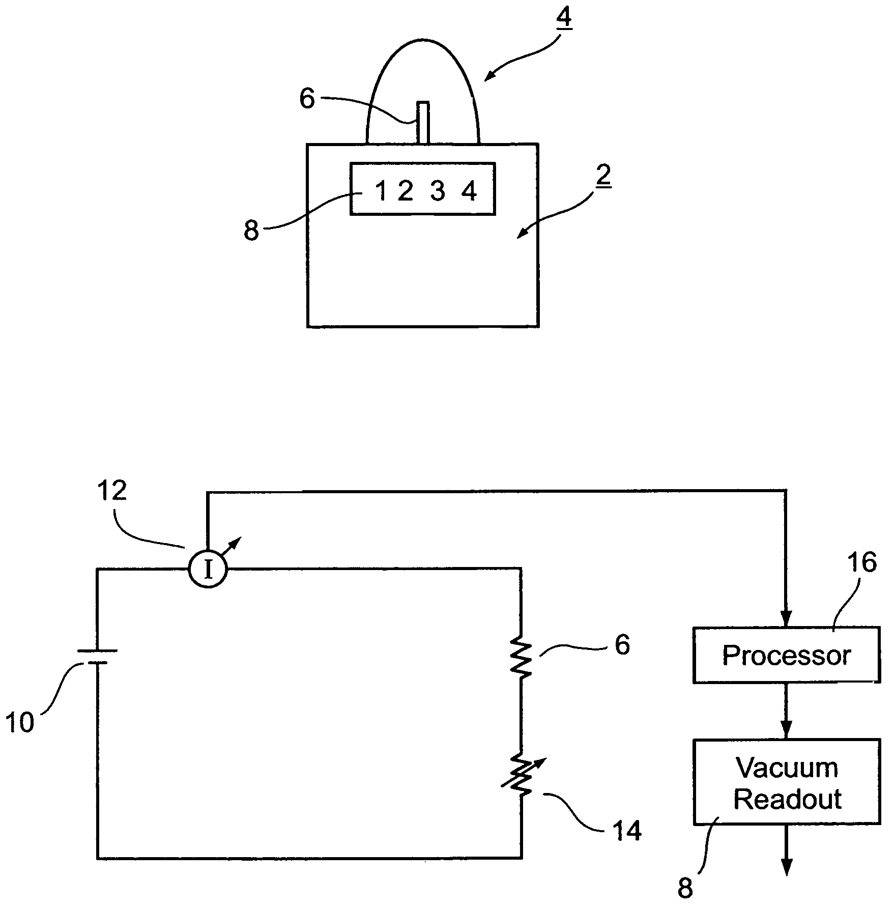
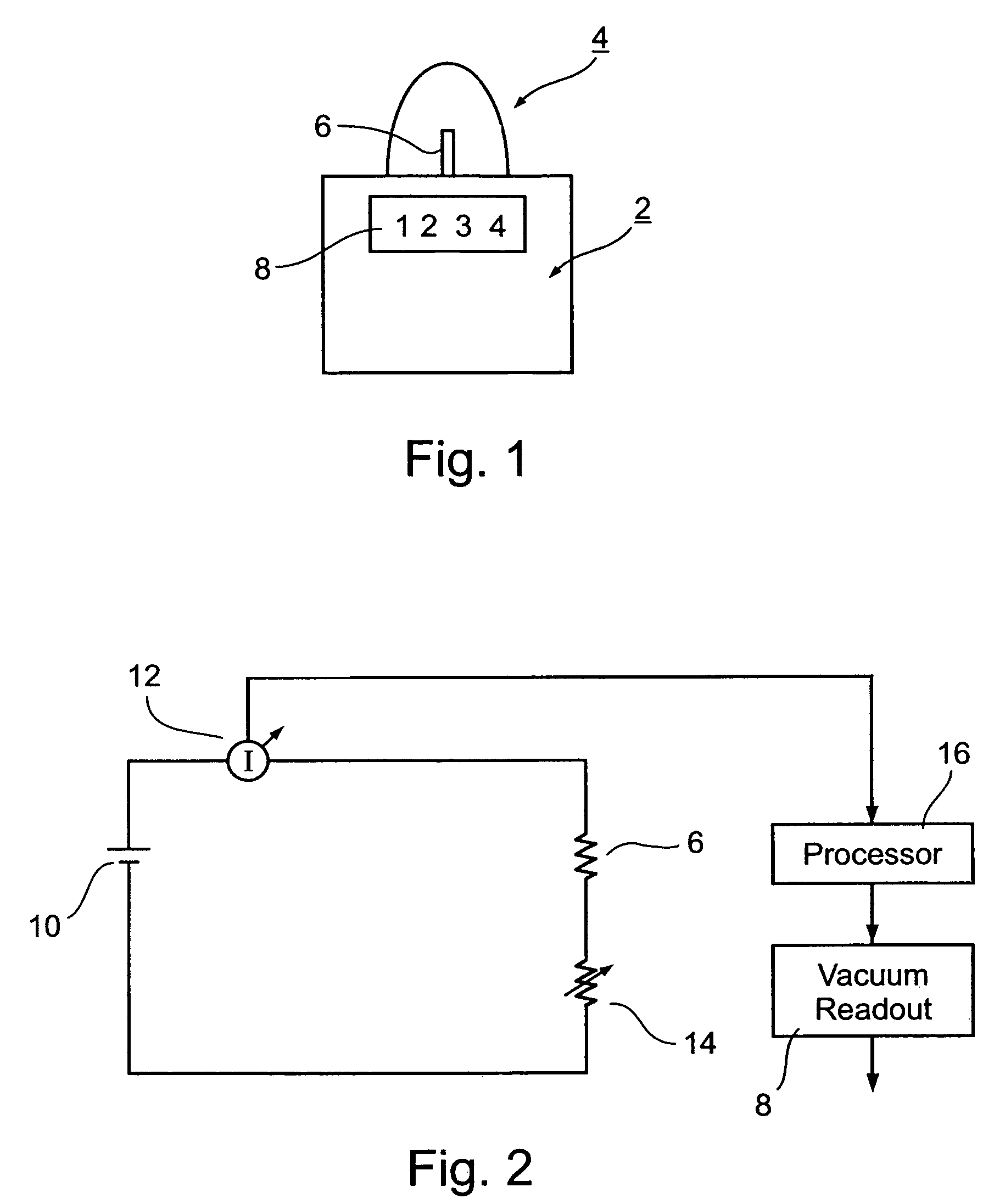
[0027]FIG. 1 illustrates a vacuum gauge constructed in accordance with the present invention for measuring the level of vacuum within a vacuum chamber VC; and FIG. 2 is a schematical diagram illustrating the electrical system included in the vacuum gauge of FIG. 1.

[0028]The illustrated vacuum gauge includes a vacuum pump, generally designated 2, of a known construction, such as a roughing pump or a diffusion pump, for producing a vacuum within the vacuum chamber VC defined by a cover 4. As will be described more particularly below with respect to FIG. 2, the vacuum chamber VC includes a positive temperature coefficient (PTC) thermistor 6 for measuring the level of the vacuum within the vacuum chamber, and a digital display 8 for reading out the measured vacuum level.

[0029]The electrical circuit included within the vacuum gauge of FIG. 1 is more particularly illustrated in FIG. 2. It includes, besides PTC thermistor 6: a voltage source 10 for supplying the PTC thermistor with electri...


PUM


Abstract

Method and apparatus for measuring the pressure of a fluid medium, by immersing within the fluid medium an electrical resistor having a resistance varying with temperature; applying electrical current through the electrical resistor to heat it to a predetermined temperature above that of the fluid medium; and measuring the rate of change in resistance of the electrical resistor to produce a measurement of the rate of thermal heat dissipation, varying with the density of the fluid medium in which the electrical resistor is immersed, and thereby a measurement of the pressure of the fluid medium. The electrical resistor is a positive temperature coefficient thermistor driven by a constant voltage source and having a resistance which increases sharply at the predetermined temperature, such that the thermistor is automatically self-controlled to substantially maintain the predetermined temperature, whereby the electrical current drawn by the thermistor is a measurement of the thermal load on the thermistor resulting from the thermal heat dissipation therefrom, and thereby a measurement of the pressure of the fluid medium. Many applications of such method and apparatus are described, including a vacuum gauge, a pressure gauge, a barometer, a Pitot tube type speedometer, and a helicopter blade leak detector.

Description

FIELD AND BACKGROUND OF THE INVENTION[0001]The present invention relates to methods and apparatus for measuring the pressure of a fluid medium capable of use in a wide variety of applications. The invention is particularly useful as a vacuum gauge, pressure gauge, barometer, altimeter, Pitot tube speedometer, and helicopter blade leak detector; and the invention is therefore described below with respect to such applications.[0002]The measurement of fluid medium pressure is utilized in many diverse applications, and many different types of pressure measuring devices have been developed for each particular application. One class of pressure measuring devices, particularly used in vacuum systems, is based on the measurement of changes in thermal conductivity accompanying changes in pressure, and thereby changes in density, of the gas. Thus, in a thermal conductivity gauge, the pressure depends on the heat conduction through the gas from a hot spot of a self-regulated source to the surr...

Claims


Application Information

Patent Timeline
IPC IPC(8): G01L9/00G01L21/12
CPCG01L21/12
Inventor GOLAN, GADY
Owner A T C T ADVANCED THERMAL CHIP TECH
Learn More