Low Cost Gold Wire Brushes

Active Publication Date: 2014-02-06
SCHLEIFRING & APPBAU
View PDF7 Cites 4 Cited by
  • Summary
  • Abstract
  • Description
  • Claims
  • Application Information

AI Technical Summary

Benefits of technology

[0007]The embodiments are based on the object of providing slipring brushes and a slipring with simplified manufacturing and r

Problems solved by technology

This results in the lar

Method used


Image

  • Low Cost Gold Wire Brushes
  • Low Cost Gold Wire Brushes
  • Low Cost Gold Wire Brushes

Examples


Embodiment Construction

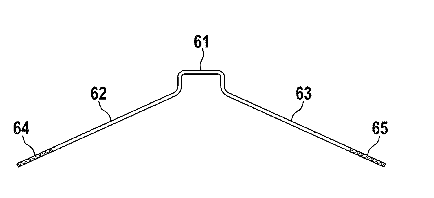
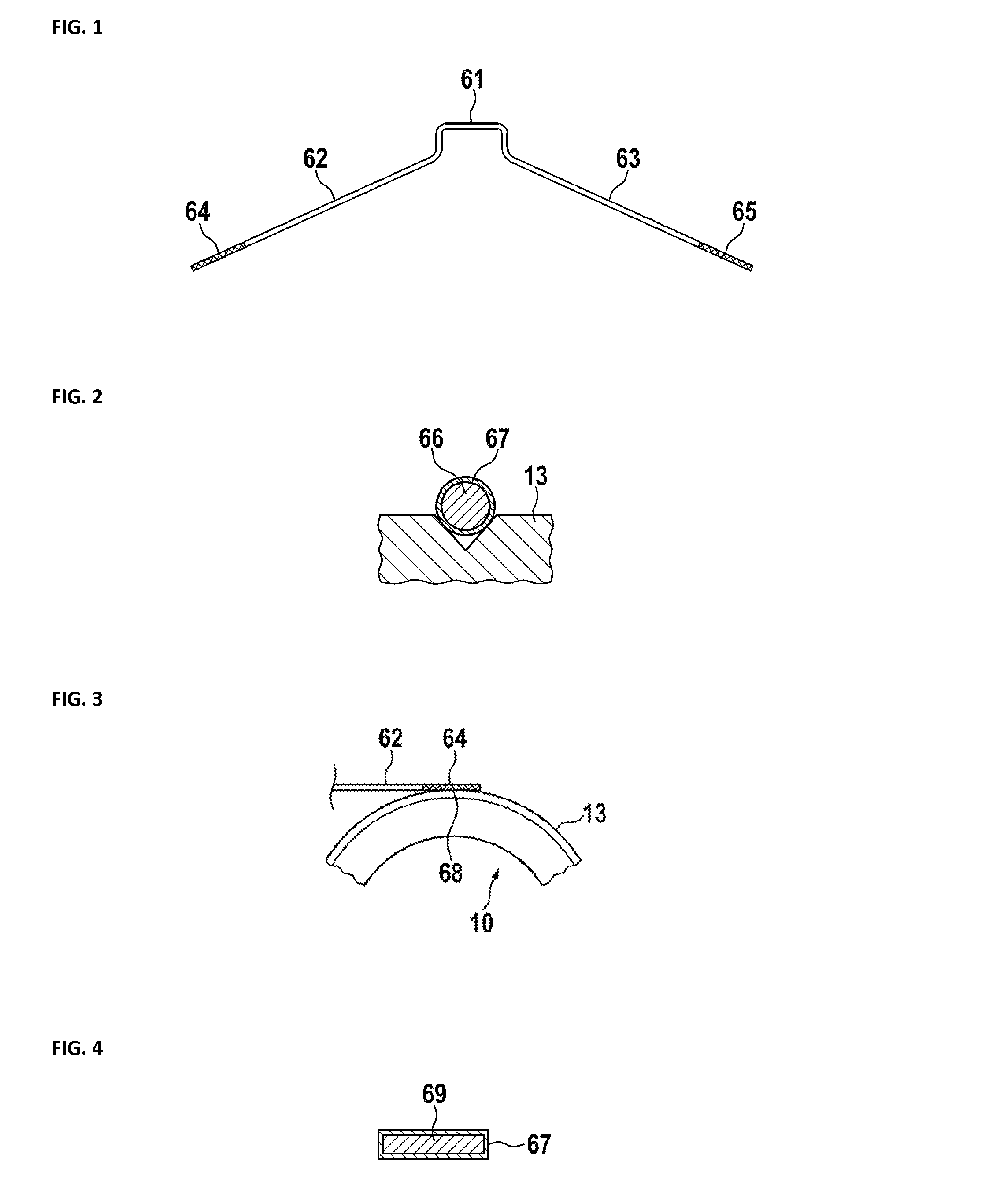
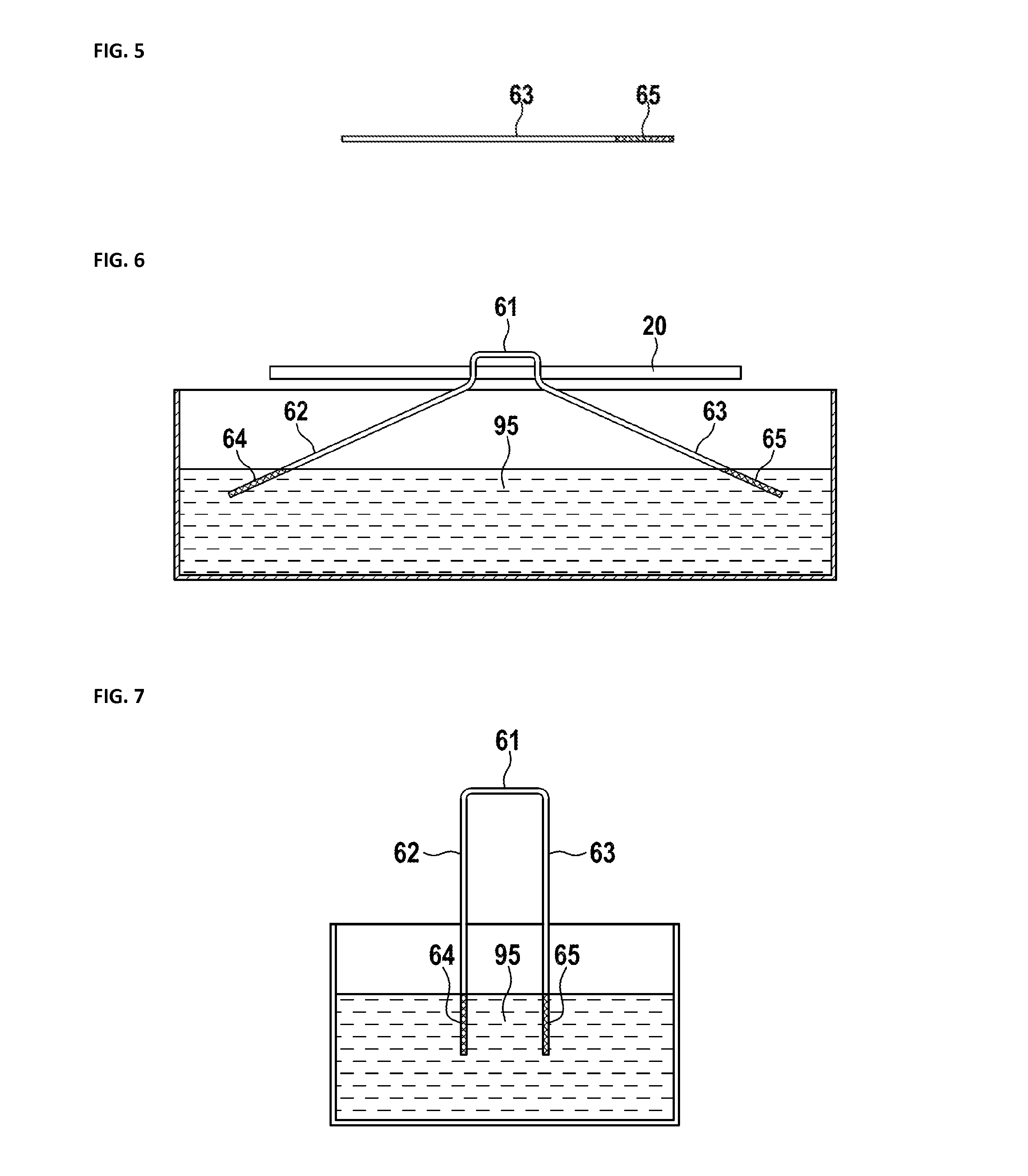
[0030]In FIG. 1, a preferred embodiment according to the invention is shown. A slipring brush has a center section 61, which may be bent to be adapted to a brush holder. On the first side of this center section is a first uncoated section 62 followed by a first coated or plated section 64, and on the second side of the center section is a second uncoated section 63 followed by a second coated or plated section 65. The first and second coated or plated sections are the sections, which are in contact with a slipring module. Contact of the uncoated section with a slipring module should be avoided, as this could cause unnecessary wear and results in poor transmission characteristics like considerably contact noise. Preferably, the coating completely encloses the coated or plated sections. Details of the coated or plated sections are shown in the next figure.

[0031]In FIG. 2, the details of a coated or plated section are shown. A wire 66 has a coated or plated surface section 67. The wire...


PUM


Abstract

A slipring brush includes a body of a metal wire or metal band having a contact area for contacting a slipring module. The contact area is selectively coated by a contact material like gold or silver or an alloy thereof. The body preferably includes Copper, Nickel, Iron, or an alloy thereof. Coating may be done by electroplating, physical vapor deposition (PVD) or chemical vapor deposition (CVD).

Description

PRIORITY CLAIM[0001]This application claims priority to pending European Patent Application No. 12179432.5 filed on 6 Aug. 2012.BACKGROUND OF THE INVENTION[0002]1. Field of the Invention[0003]The invention relates to an electrical power transfer device like a slipring or rotary joint and brushes thereof. Sliprings are used to transfer electrical power between rotating parts of machines like wind power plants, CT scanners or electrical generators. There a brush, mainly including electrically conductive material like a metal is sliding on a rotating cylindrical track of conductive material like brass, which may have gold plating.[0004]2. Description of Related Art[0005]The European patent application EP 0054380 A1 discloses a slip ring and brush assembly. The brush includes a bundle of thin electrically conducting fibers, which project from a brush holder to contact the slipring. The annular contact surface of the slipring is provided by a gold layer thereon. By making the fibers of a...

Claims


Application Information

Patent Timeline
IPC IPC(8): H01R39/24
CPCH01R39/24H01R13/33H01R39/20H01R43/12
Inventor WINKLER, MAXHOLZAPFEL, CHRISTIAN
Owner SCHLEIFRING & APPBAU
Why Eureka
Try Eureka