Self-guiding wind turbine

a self-guiding, wind turbine technology, applied in the direction of propellers, propulsive elements, water-acting propulsive elements, etc., can solve the problems of low-power air-pump, inconvenience of assembly and maintenance, and effect on the whole structure, so as to eliminate the effect of gyroscopic effects

Inactive Publication Date: 2005-12-13
ANTOUNE IVAN LAHUERTA
View PDF9 Cites 62 Cited by
  • Summary
  • Abstract
  • Description
  • Claims
  • Application Information

AI Technical Summary

Benefits of technology

[0018]In accordance with an embodiment of the invention, a wind turbine, having a self-guiding windward design, includes a boomerang-shaped structure, balanced at a bottom end thereof by a usable platform serving as a counterweight and at an upper end thereof by a rotor head, the rotor head being located in such a way that a center of gravity of a rotor is on a vertical axis of a column on which the structure pivots, thus eliminating gyroscopic effects. When the rotor and the rotor head are required to tilt due to axial thrust, the rotor and the rotor head tilt, while the structure remains stationary.
[0019]In some embodiments, the wind turbine is characterized in that the rotor comprises a self-stabilizing two-bladed rotor which improves self-guiding of the wind turbine whilst in action due to the fact that the rotor is in a shape of a dihedral having an axial center of thrust situated behind, seen in a direction of incidental wind, a center of gravity of the rotor, giving the rotor independent stability. In accordance with this embodiment, the wind turbine is also characterized in that an application point of axial thrust is situated behind, seen in the direction of the incidental wind, a rotation axis of the column on which the structure pivots so as to improve self-guiding of the wind turbine whilst the wind turbine is in action. In accordance with this embodiment, the wind turbine is further characterized in that the two-bladed rotor is supported by a fork-bolt assembly situated on an axis that goes through the rotor's center of gravity, allowing the rotor to oscillate, and minimizing, due to a shock absorber, pitching moments generated by the incidental wind in low attack angles and continuous direction changes and at different speeds between upper and lower blades of the rotor. The wind turbine is further characterized in that the two-bladed rotor is configurable to have a w-shape when it is required that the center of gravity remain within the two-bladed rotor.
[0020]In some embodiments, the wind turbine is characterized in that internal elements of a multiplier do not support axial thrust, pitching moments, or vibrations from the rotor, since the fork-bolt assembly responsible for transmitting motor pair, the axial thrust, the pitching moments and the vibrations from the rotor is fixed on a movable hoop of a large bearing, the fixed hoop of the bearing being linked externally to a clamp which fastens a chassis of the multiplier, which is an epicycloidal multiplier, so that the axial thrust, the pitching moments and the vibrations are transmitted from the fork-bolt assembly to the chassis of the multiplier without passing through a primary axis of the multiplier, whereby durability of axes, bearings and cogs of the multiplier is enhanced.

Problems solved by technology

Nevertheless, there is a large number of low-power air-pumps and aero-generators that make up a very small part (of little importance) of total installations.
Despite the confirmed good functioning in generating and using wind, structurally there are various problems due to the shadow of the towers on the blades, the gyroscopic moments created because the center of gravity of the rotor is displaced with respect to the rotation axis, specific weights in the order of 14 kg / m2 and the pitching moments due to constant changes in wind direction and differences in speed between the upper and lower blades, which have an effect on the whole structure, weakening it when endowed with rigid rotors, as well as the inconvenience of assembly and maintenance at high altitudes.
If we compare values of aero-generators of 45 m in diameter (600 kW of nominal power) and 60 m in diameter (1 MW of nominal power), there is an increase of more than 30%, which has an effect on the specific cost (total cost / area swept) as well as a 35% increase in the costs of the installed kW.
The rotors used are usually slow rotors with speeds at the end of the blades of 55 m / s, their rotation level being five meters from the column of the axis they pivot on, and produce gyroscopic effects that tend to destabilize the machine.
Nevertheless, as rotor diameter increases, so does the number of two-bladed aero-generators, which are usually designed to be used to leeward and where the shadow effect of the tower on the blades is more noticeable, thus producing significant stresses and vibrations.
Wind change controls are equipped with complex moving parts and the corresponding risk of failure and greater maintenance needs.
The height of towers is inconvenient when it comes to assembling and maintaining them.
Moreover, the fact that the generator is situated on the gondola, which revolves, results in the problem of how to transmit power to the ground through cables.
However, increased wind speed may not compensate the increase in manufacturing costs if, keeping current technical design concepts, attempts are made to design machines with diameters larger than the rotor's 50 m. This is due to the fact that the main pressure on aero-generators depends on the cube of the rotor diameter, the weight and manufacturing costs increasing in the same manner, while the increase in energy produced increases with the area of the rotor.
On the other hand, specific costs of transportation, assembly, operating and maintenance of these high-power machines are greater than those of aero-generators currently on the market.

Method used


Image

  • Self-guiding wind turbine
  • Self-guiding wind turbine
  • Self-guiding wind turbine

Examples


Embodiment Construction

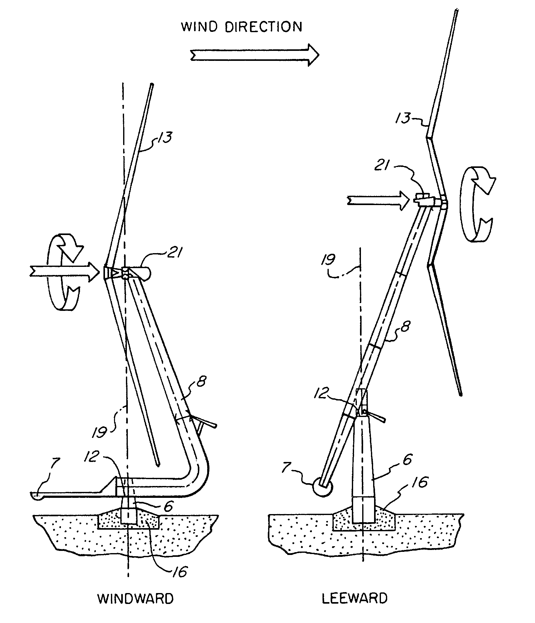
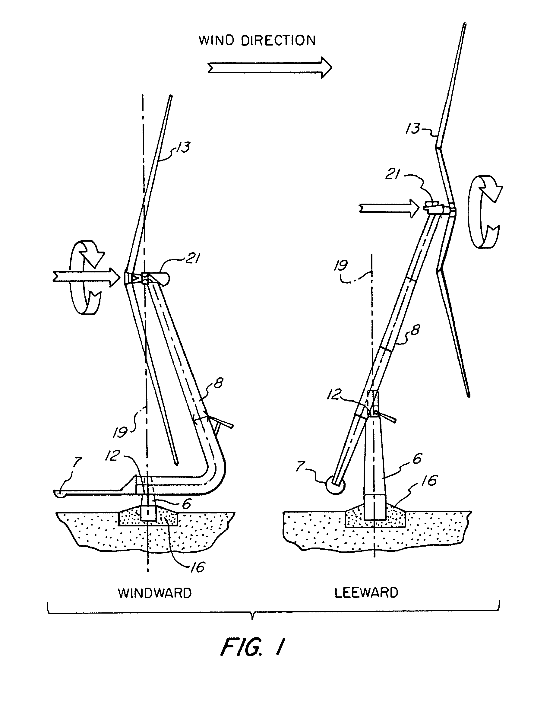
[0036]Referring to FIGS. 1–8, in the present invention, we are attempting to use wind energy with simpler turbines than the classical turbines currently on the market, putting forward a self-guiding design that confers complete freedom when it comes to positioning itself in the direction of the wind, taking better advantage of the incidental current energy, whose force is used not only to capture power but also to protect it, avoiding the necessity to overcome forces and moments superior to those calculated. The design of said self-guiding structure, formed of two reinforced parallel girders positioned on their side in the form of a “grating”, has a section protruding less in the head-on direction of the wind (machine in position), allowing the wind to pass through, encountering less resistance and simultaneously reducing the shadow effect on the blade and making it self-guiding given that its center of thrust is moved sideways with respect to the rotation axis of the column it is s...


PUM


Abstract

A self-guiding wind turbine made of two reinforced parallel girders whose side center of thrust is displaced from the column axis where it is supported and turns. Its dihedral-shaped two-bladed rotor is self-stabilizing since its center of thrust is behind its center of gravity and the guiding axis of the turbine, thus improving self-guiding whilst in motion. The axial thrust is controlled, whilst the head and rotor are tilting, hydraulically by counter-pressure, ensuring they do not surpass the power collected and the moments on the structure, shoe and ground. The self-guiding structure can tilt hydraulically lowering its head and rotor and facilitating its assembly and maintenance, and can remain “asleep” when not in use, thus reducing the visual impact on the environment. This turbine makes use of the force of the wind to control itself, simplifying the manufacture of large turbines connected to the network or in isolated applications.

Description

[0001]This application is a continuation of pending International Patent Application No. PCT / ES02 / 00303 filed Jun. 11, 2002 which designates the United States and claims priority of pending Spanish Application No. P200101404 filed Jun. 12, 2001.FIELD OF THE INVENTION[0002]The present invention refers to a novel design for a self-guiding wind turbine, in which an attempt is made to simplify the execution of this type of machine, equipping it with a greater degree of freedom, giving it self-guiding structures and self-stabilizing rotors, where the force of the wind itself is used to protect them instead of destroying them, given that they are already working “for the air current,” better using said force and ensuring that the structure, shoe or ground can withstand forces greater than the nominal. The attribute that the structure can tilt, even to the point where the head and rotor are very near the ground, reduces the time and cost of assembly and maintenance, as well as the necessar...

Claims


Application Information

Patent Timeline
Patent Type & Authority Patents(United States)
IPC IPC(8): F03D7/02F03D13/20
CPCF03D7/0208F03D7/0212F03D7/0216F03D11/04F05B2240/9152Y02E10/723Y02E10/728F03D13/20F03D9/20F03D80/70Y02E10/72Y02P70/50
Inventor ANTOUNE, IVAN LAHUERTAANTOUNE, SEBASTIAN MANUEL LAHUERTAANTOUNE, MARIA LAHUERTA
Owner ANTOUNE IVAN LAHUERTA
Why Eureka
Try Eureka