
Method and apparatus for electrochemical planarization of a workpiece

Inactive Publication Date: 2005-12-13
NOVELLUS SYSTEMS
View PDF25 Cites 7 Cited by
  • Summary
  • Abstract
  • Description
  • Claims
  • Application Information

AI Technical Summary

Benefits of technology

[0018]In accordance with a further embodiment of the present invention, the electrolytic planarizing solution includes a film forming agent for facilitating the formation of a passivation layer on the metallized surface of the workpiece.

Problems solved by technology

Over time, the semiconductor industry has slowly been moving to the use of copper for metallization due to the alloying and electromigration problems that are seen with aluminum.
While CMP tends to work very well for planarization if the correct slurry and process parameters are used, it may leave stresses in the worked workpiece, leading to subsequent cracking and shorting between metal layers.
In addition, the semiconductor industry is increasingly using low k dielectrics, which tend to be fragile materials.
CMP may result in shearing or crushing of these fragile layers.
CMP also has a tendency to cause dishing in the center of wide metal features, such as trenches and vias, oxide erosion between metal features, and oxide loss of the dielectric.
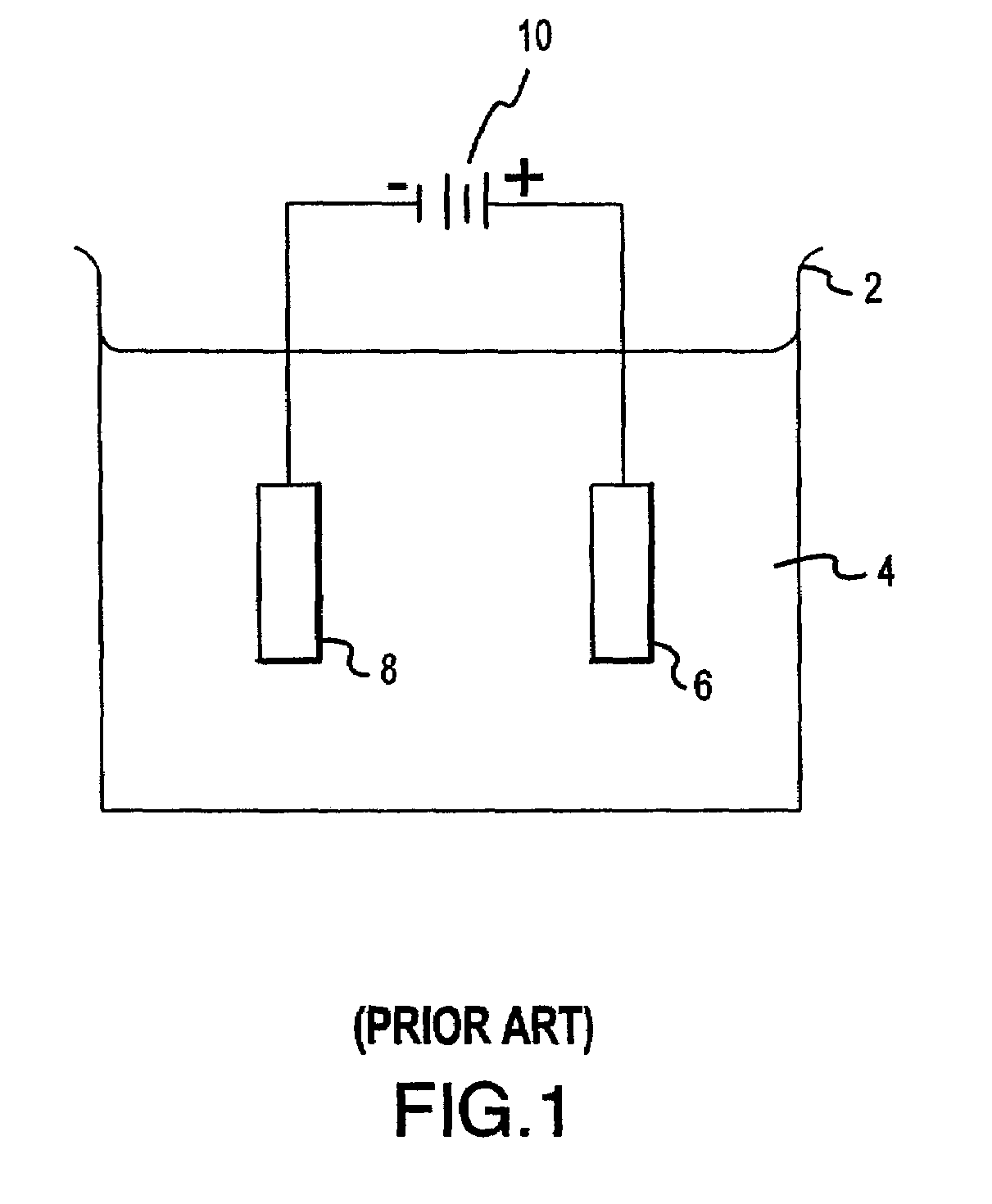
When used for planarization of metal films on semiconductior wafers, conventional electrochemical planarization presents the disadvantage that the metal may not be selectively removed from the wafer.
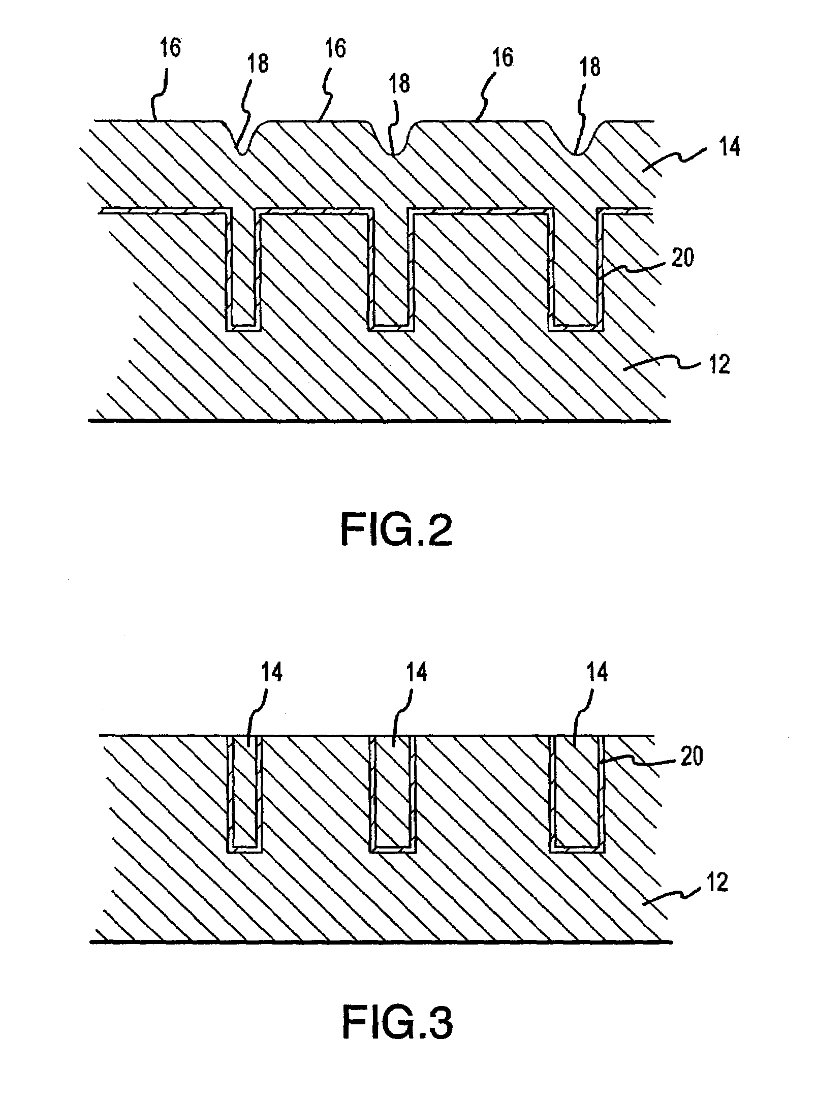
While existing electrochemical planarization techniques are known to “smooth” a metal layer, they are limited by topography dimensions and do not achieve true planarization. FIG. 2 shows a dielectric layer 12 having trenches, or vias, and having a barrier metal layer 20 thereon.
Thus, with conventional electrochemical planarization, uniform planarization is not achieved.

Method used


Image

  • Method and apparatus for electrochemical planarization of a workpiece
  • Method and apparatus for electrochemical planarization of a workpiece
  • Method and apparatus for electrochemical planarization of a workpiece

Examples


Embodiment Construction

[0035]The following description is of exemplary embodiments only and is not intended to limit the scope, applicability or configuration of the invention in any way. Rather, the following description provides a convenient illustration for implementing exemplary embodiments of the invention. Various changes to the described embodiments may be made in the function and arrangement of the elements described without departing from the scope of the invention as set forth in the appended claims.

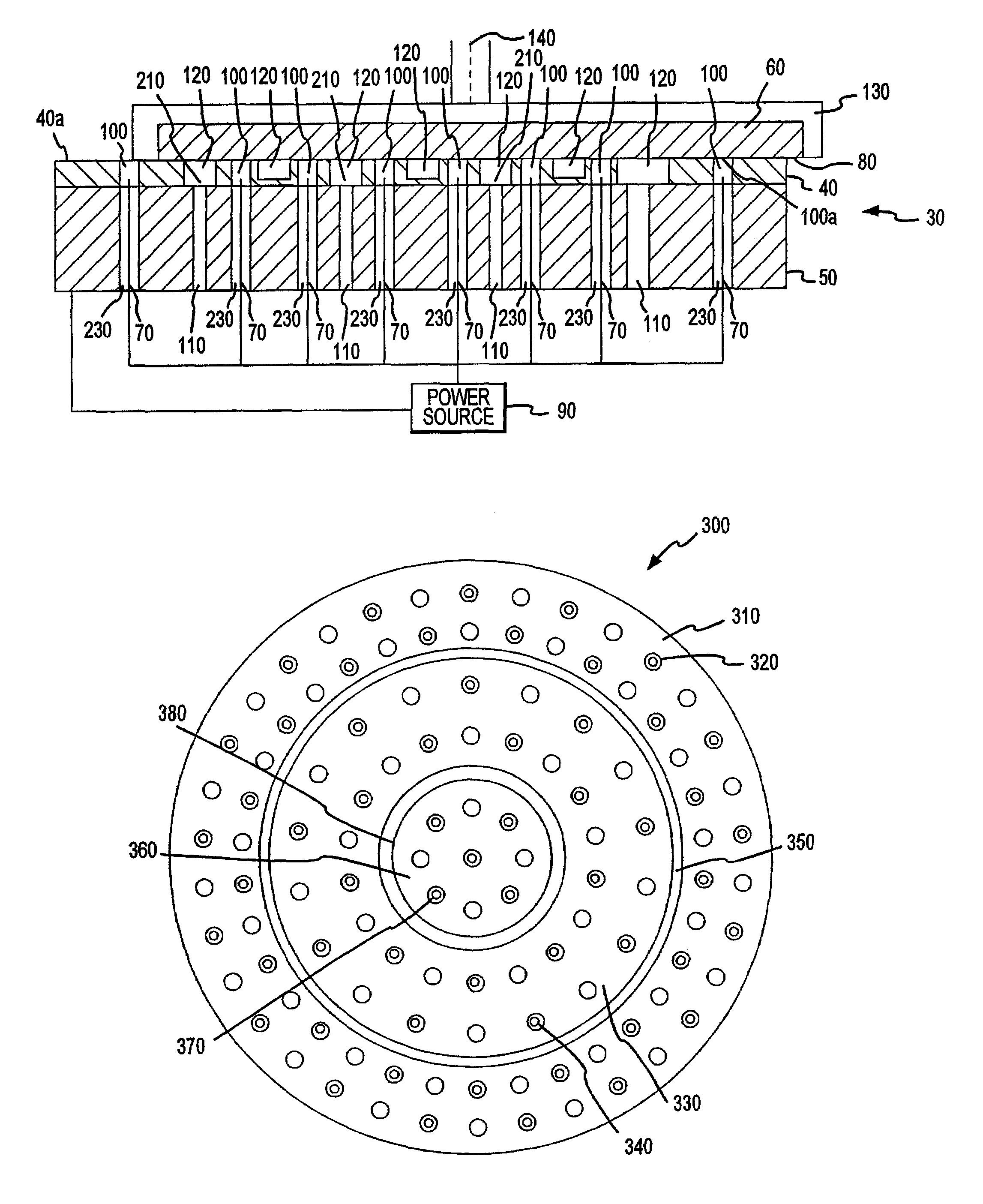
[0036]A schematic representation of an exemplary embodiment of an electrochemical planarization (ECP) apparatus 30 of the present invention is illustrated in FIG. 4. The ECP apparatus 30 may use chemical mechanical planarization (CMP) in addition to electrochemical etching to planarize the metallized surfaces of workpieces. To effect electrochemical etching, ECP apparatus 30 utilizes an insulative polishing pad 40 supported by a platen 50. A wafer 60 with a metallized surface 80 may be urged against ...


PUM

PropertyMeasurementUnit
Distanceaaaaaaaaaa
Distanceaaaaaaaaaa
Electrical conductivityaaaaaaaaaa

Abstract

An electrochemical planarization apparatus for planarizing a metallized surface on a workpiece includes a polishing pad and a platen. The platen is formed of conductive material, is disposed proximate to the polishing pad and is configured to have a negative charge during at least a portion of a planarization process. At least one electrical conductor is positioned within the platen. The electrical conductor has a first end connected to a power source. A workpiece carrier is configured to carry a workpiece and press the workpiece against the polishing pad. The power source applies a positive charge to the workpiece via the electrical conductor so that an electric potential difference between the metallized surface of the workpiece and the platen is created to remove at least a portion of the metallized surface from the workpiece.

Description

CROSS REFERENCE TO RELATED APPLICATIONS[0001]This patent application claims the benefit of and is a continuation of application Ser. No. 09 / 781,593 filed in the United States Patent and Trademark Office on Feb. 12, 2001 now U.S. Pat. No. 6,736,952.FIELD OF INVENTION[0002]The present invention relates, generally, to systems for polishing or planarizing workpieces, such as semiconductor wafers. More particularly, it relates to an apparatus and method for electrochemical planarization of a wafer having a metallized surface.BACKGROUND OF INVENTION[0003]The production of integrated circuits begins with the creation of high-quality semiconductor wafers. During the wafer fabrication process, the wafers may undergo multiple masking, etching, and dielectric and conductor deposition processes. In addition, metallization, which generally refers to the materials, methods and processes of wiring together or interconnecting the component parts of an integrated circuit located on the surface of a ...

Claims


Application Information

Patent Timeline
IPC IPC(8): B23H5/08B24B37/12B24B37/20H01L21/321
CPCB23H5/08B24B37/12B24B37/20C25F3/02C25F7/00H01L21/32125H01L21/7684
Inventor EMESH, ISMAILCHADDA, SAKETKOROVIN, NIKOLAY N.MUELLER, BRIAN L.
Owner NOVELLUS SYSTEMS
Learn More