Unlock instant, AI-driven research and patent intelligence for your innovation.

Circuit for direct digital delta-sigma conversion of variable electrical capacitance

Active Publication Date: 2005-12-13
FOR NAT RES INITIATIVES
View PDF11 Cites 6 Cited by
  • Summary
  • Abstract
  • Description
  • Claims
  • Application Information

AI Technical Summary

Benefits of technology

[0010]It is an object of the present invention to provide a circuit that can convert a capacitive transducer signal directly to a digital representation that can be fed directly to a digital signal processor (DSP).

Problems solved by technology

The use of capacitive transducers is very prevalent because they provide unparalleled performance in terms of size, low inherent self-noise and power consumption.
The problem with capacitive transducers, however, is that the output impedance is so high that the signal conditioning circuit 102 used to read out the transducer signal must have extremely high input impedance, so that it does not load, and thereby dampen, the already small sensor signal.
The most important drawbacks are poor power supply rejection and sensitivity to parasitic capacitances (Cp in FIG. 2) between the transducer capacitance Ct and the amplifier 200.
The most important drawbacks of the charge amplifier circuit 300 are the power consumption and the relatively high required supply voltage.
The major drawbacks of the AM circuit are high power consumption, high required supply voltage, and the need for a harmonic voltage source.
Implementing harmonic voltage sources with low amplitude noise is a challenging task.
While circuit 500 can be built to perform with very low self-noise, it requires analog circuitry and amplifiers, which cannot be readily integrated with a DSP on the same chip, due to limitations in integrated circuit manufacturing.
The problem with this digital detection circuit 600 is that the FM output is not directly compatible with the input required on a DSP, and would hence require extra processing, such as up or down conversion, to be used.

Method used


Image

  • Circuit for direct digital delta-sigma conversion of variable electrical capacitance
  • Circuit for direct digital delta-sigma conversion of variable electrical capacitance
  • Circuit for direct digital delta-sigma conversion of variable electrical capacitance

Examples


Embodiment Construction

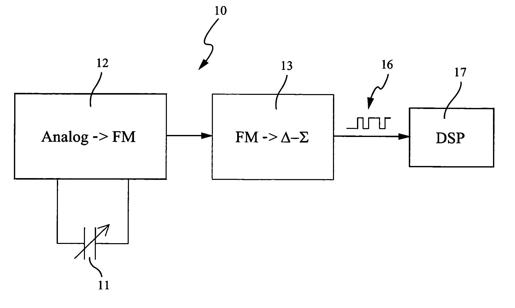
[0029]One embodiment of a direct delta-sigma conversion circuit 10 according to the present invention is shown in the block diagram of FIG. 8, and in the more detailed circuit diagram of FIG. 9. Circuit 10 preferably consists of a capacitive transducer 11 and two functional blocks 12 and 13. Functional block 12 converts changes in capacitance within capacitive transducer 11 to a frequency modulated digital signal, the frequency of which depends directly on the instantaneous capacitance of transducer 11. Transducer 11 can be wired to functional block 12 using bond pads (not shown) or it can be monolithically integrated with conversion circuit 10. Functional block 13 converts a frequency modulated digital signal to a delta-sigma digital bit stream 16, in which the instant frequency of the FM signal from functional block 12 is represented. A common important feature for functional blocks 12 and 13 is that they are implemented using components readily available in any commercial integra...


PUM


Abstract

An electronic circuit for the direct conversion of a capacitive transducer signal to a digital delta-sigma bit stream is disclosed. The electronic circuit is comprised of two functional blocks, in which the variable transducer capacitance is first transformed and represented by a frequency modulated (FM) signal by a variable frequency oscillator, and subsequently converted to a digital delta-sigma representation using a frequency delta-sigma modulator. The electronic circuit eliminates any need for analog components in conjunction with the capacitive transducer, and hence simplifies the front-end circuit for applications where digital signal processing (DSP) is used. The output bit stream of the electronic circuit is similar to other analog to digital delta-sigma converters, and can therefore be processed using similar digital techniques.

Description

CROSS-REFERENCE TO RELATED APPLICATION[0001]This application claims the benefit of Provisional Application No. 60 / 441,768, filed Jan. 23, 2003, the entire contents of which is hereby incorporated by reference in this application.FIELD OF THE INVENTION[0002]The present invention relates to electronic instrumentation circuitry, and more specifically to circuits used to determine and measure the static or dynamic change of electrical capacitance in capacitive or electrostatic transducers.BACKGROUND OF THE INVENTION[0003]Rapid developments in digital signal processing is one of the main development drivers in many systems containing acoustic detectors. In these types of systems 100 (see FIG. 1), an analog signal from an acoustic transducer 101 is normally converted into the digital domain using some analog signal conditioning circuit 102 and a multi stage delta-sigma converter 103. The digital signal is then processed by a processor 104 and subsequently converted back to an analog signa...

Claims


Application Information

Patent Timeline
IPC IPC(8): H03M3/00H03M3/02
CPCH03M3/39H03M3/43H03M3/456
Inventor PEDERSEN, MICHAEL
Owner FOR NAT RES INITIATIVES