Lubrication system for a power plant

a lubrication system and power plant technology, applied in the direction of pressure lubrication with lubrication pump, engine lubrication, mechanical equipment, etc., can solve the problems of reducing engine output, air may remain in the crankcase, and other chambers connected to the crankcase are not maintained under negative pressure (or vacuum), so as to improve engine efficiency and lubricant quality, and improve the quality of lubricant. , the effect of dripping more efficiently

Inactive Publication Date: 2005-12-27
BRP ROTAX
View PDF15 Cites 5 Cited by
  • Summary
  • Abstract
  • Description
  • Claims
  • Application Information

AI Technical Summary

Benefits of technology

[0017]It is, therefore, an aspect of embodiments of the present invention to provide a construction for an engine which provides improved drainage of lubrication and blow-by gases from the various engine chambers.
[0027]An additional aspect of the present invention provides a power unit where the lubrication system is preferably a dry sump lubrication system. The negative pressure permits lubricant to be drained more efficiently from different engine areas such as the crankcase, the gearbox housing, and other engine casing parts by creating a negative pressure within each of the different engine areas. This arrangement improves engine efficiency and lubricant quality by providing better degassing of the lubricant. The present invention further reduces the oil tank volume.
[0028]In accordance with the present invention, the at least one drainage line may include a plurality of drainage lines, which extend to the lubrication tank, the gearbox and additional compartments within the power plant that are also partitioned or isolated from the gearbox and the crank chamber. A first drainage line may extend from the crank chamber, wherein the first drainage line is operatively connected to the lubrication tank to drain blow-by gas and lubricant from the crank chamber. A second drainage line extend from the crank chamber to the gear box to supply blow-by gas to the gearbox. It is possible to also drain lubricant from the crank chamber to the gearbox. The second drainage line may be operatively connected to a secondary air supply. The secondary air supply increases the amount of air supplied to the gearbox to improve scavenging within the gearbox.
[0029]The present invention is not intended to be limited to supplying blow-by gas to just the gearbox to improve the drainage of lubricant therefrom. Blow-by gas can be supplied from the crank chamber to other engine compartments. The blow-by gas can be supplied in parallel such that it is separately fed into the gearbox and the additional compartments or the gas can be supplied in series such that it is from one compartment into the next. The crank chamber, the gear box and the additional compartments can be separately drained by drainage lines that extend from each compartment or they can be drained in series whereby lubricant and blow-by gas is first drained from the crank chamber into the gearbox or adjacent compartment and then into subsequent compartments. In either case, at least one suction pump is provided to create a negative pressure to improve the flow of lubricant and blow-by gas. Due to the improved drainage of lubricant from the engine cases and chambers, the total oil quantity can be used more efficiently, and, consequently, the oil tank volume can be reduced and engine volume reduced.
[0030]The present invention is also directed to a method of recirculating lubrication in a power plant. The method includes supplying lubricant from the lubrication tank to the crank chamber and the gearbox. The lubricant is drained from the crank chamber and the gearbox under the influence of a negative pressure. The lubricant is then returned to the lubrication tank. Blow-by gas is transferred from the crank chamber to the gearbox to improve drainage of lubricant from the gearbox.

Problems solved by technology

Other chambers connected to the crankcase, however, are not maintained under a negative pressure (or vacuum), because those skilled in the art do not perceive a benefit to such a construction.
One drawback of the system described in this European patent lies in the fact that air may remain present in the crankcase during operation of the engine.
When the engine is running, movement of the piston during intake (suction) and combustion (explosion) and the rotational motion of the connecting rod and the crankshaft are disturbed by the air in the crankcase, which reduces engine output.
Furthermore, the air in the crankcase deteriorates the quality of the operation of the engine, because it may cause the lubricant to oxidize or deteriorate, which reduces the quality of the lubricant.
There have been numerous attempts to separate the crank chamber from other engine chambers, but none disclose maintaining two or more of these chambers under negative pressure.
As indicated above, those skilled in the art do not recognize the benefit of such a construction.
This arrangement is necessary because the transmission case cannot be positioned below the oil level in the lubrication tank.
One problem that is presented by the prior art lies in the fact that those skilled in the art have focused on separating the crankcase from the other chambers associated with the engine.

Method used


Image

  • Lubrication system for a power plant
  • Lubrication system for a power plant
  • Lubrication system for a power plant

Examples


Embodiment Construction

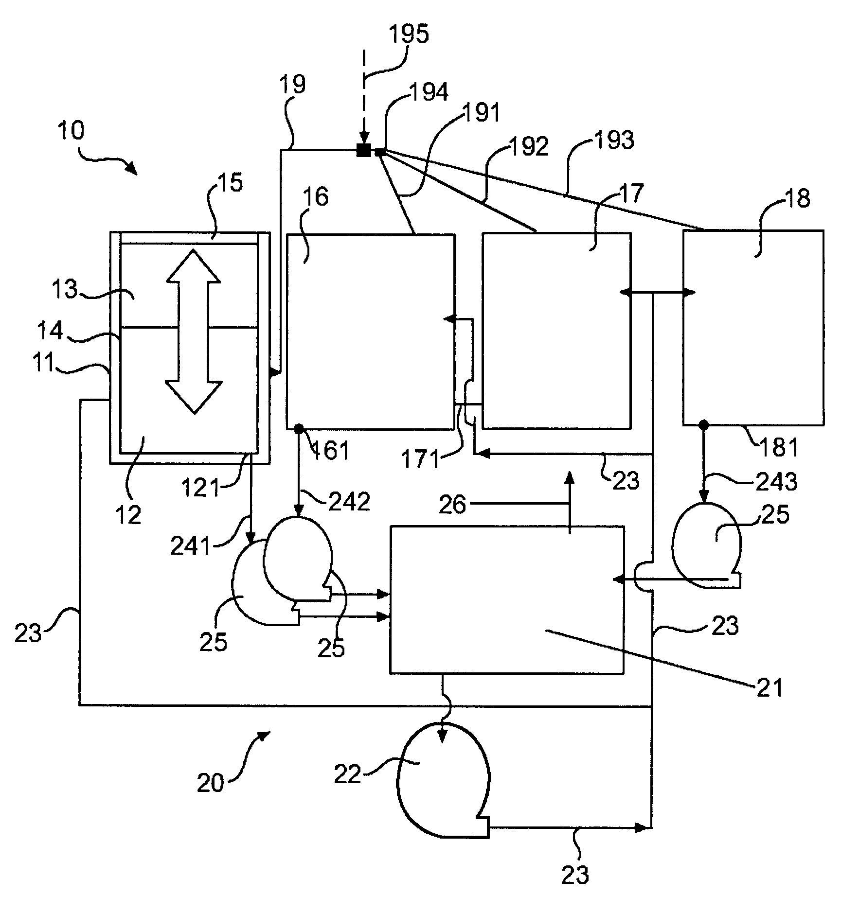
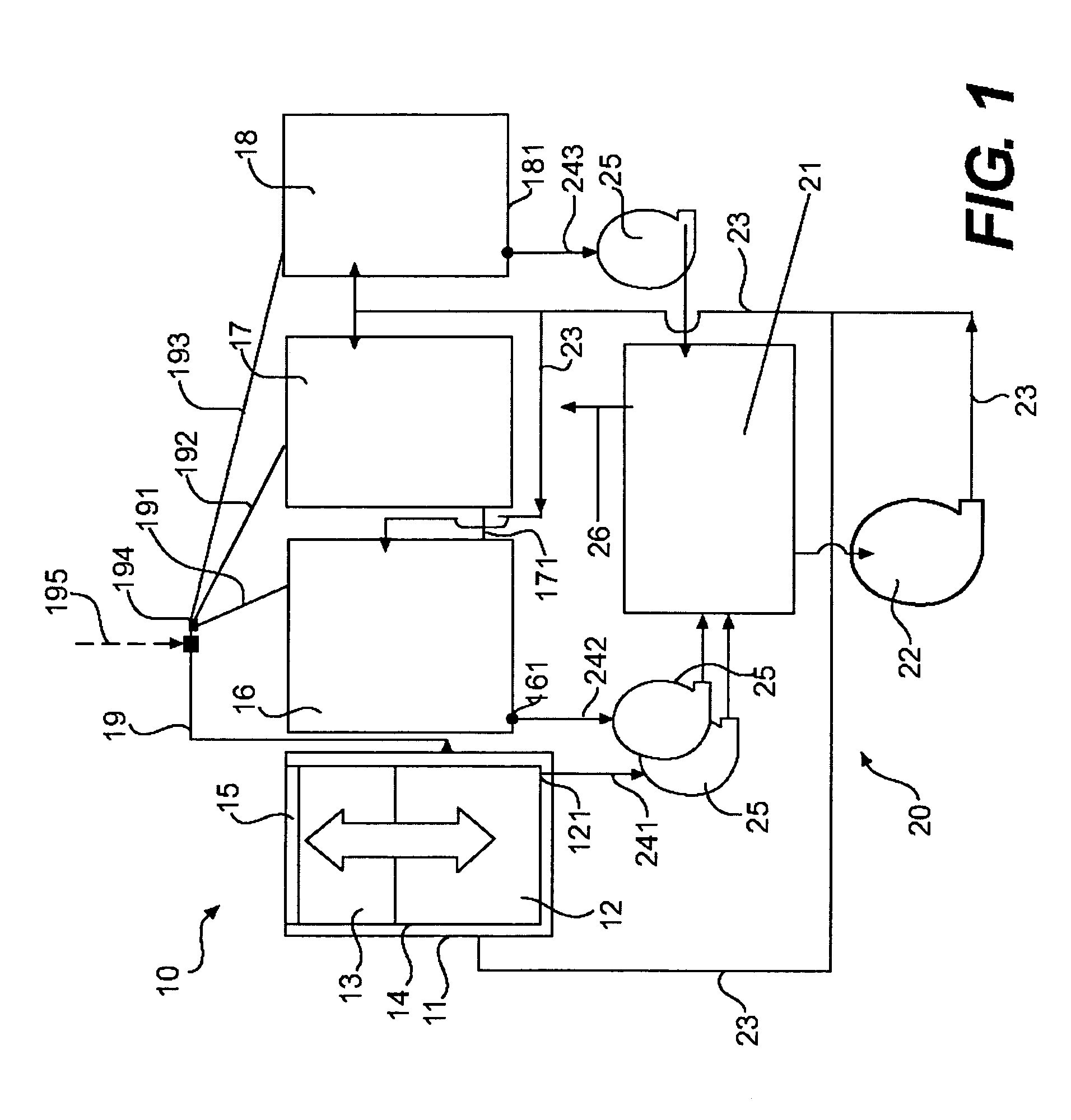
[0036]A dry sump lubrication system in accordance with one embodiment of the present invention will now be described in greater detail in connection with FIG. 1. An internal combustion engine and a gearbox are combined to form a power plant or common drive unit 10 having a common dry sump lubrication circuit 20. The drive unit 10 includes a crankcase 11 having crank chamber 12 formed therein. The crank chamber 12 houses the crankshaft (not shown) and the piston arm (not shown), which are operatively connected to a piston 13.

[0037]The crankcase 11 includes at least one cylinder 14. However, the present invention is not limited to power plants 10 with only one cylinder 14. The crankcase 11 may include one, two or more cylinders 14. The cylinders may have either an in-line arrangement or a V-type arrangement. A piston 13 is located within each cylinder 14. The piston 13 is slidably disposed in the cylinder 14 and, by its operation, defines a combustion chamber 15 therein.

[0038]The driv...


PUM


Abstract

A power unit is described that combines an internal combustion engine and a lubrication system. The internal combustion engine includes a crankcase suction chamber and a transmission case suction chamber. At least one partition separates the crankcase suction chamber from the transmission case suction chamber. The lubrication system supplies lubricant to the internal combustion engine. The lubrication system includes a lubrication tank and a supply line for supplying lubricant to the internal combustion engine. At least one crankcase drainage line extends from the crankcase to drain a fluid from the crankcase suction chamber and transfer the fluid to the transmission case suction chamber. At least one pump operatively connects to one of either the crankcase chamber or the transmission case chamber. By the operation of the at least one pump, a negative pressure within at least one of the crankcase chamber and the transmission case chamber is created.

Description

CROSS-REFERENCE TO RELATED APPLICATIONS[0001]This application claims priority to U.S. Provisional Patent Application Ser. No. 60 / 410,796, entitled “Lubrication System,” filed on Sep. 16, 2002, the disclosure of which is specifically incorporated herein by reference.FIELD OF THE INVENTION[0002]The present invention relates to a dry sump lubrication system for a power plant having an internal combustion engine and a gearbox for use in numerous vehicles including but not limited to snowmobiles, personal watercraft, motorcycles, three-wheeled vehicles, go-karts, all terrain vehicles, scooters and the like. In particular, the present invention relates to a lubrication system for a power plant in which negative pressure is created in the crankcase and other compartments or areas of the engine to remove lubricant and blow-by gases in a well defined manner. The dry sump lubrication system in accordance with the present invention may be used in either a two cycle engine or a four cycle engin...

Claims


Application Information

Patent Timeline
Patent Type & Authority Patents(United States)
IPC IPC(8): F01M1/12
CPCF01M1/12F01M2001/126
Inventor KORENJAK, NORBERTLEIBER, STEFAN
Owner BRP ROTAX
Why Eureka
Try Eureka