System and method for improved stent retention

a technology for stents and stents, applied in the field of endoarterial prosthesis, can solve the problems of large number of patients subject to restnosis in the treated artery, large number of patients who require immediate medical attention, and large amount of internal flaps which can collapse and occlude the artery, so as to improve the retention of implantable medical devices, increase and improve the effect of frictional contact and interferen

Inactive Publication Date: 2005-12-27
ABBOTT CARDIOVASCULAR
View PDF96 Cites 148 Cited by
  • Summary
  • Abstract
  • Description
  • Claims
  • Application Information

AI Technical Summary

Benefits of technology

[0010]This invention is directed to an improvement in stent delivery systems for removably securing a stent onto an expandable member. Stent delivery systems are typically composed of an elongated tubular member, or catheter, encompassed by an expandable member such as an inflatable balloon. The stent is located about the expandable member so that the two can be expanded together. Securing the stent is accomplished by tightly crimping the stent onto the balloon portion of a catheter. The present invention provides an implantable medical device, such as a stent, and methods for manufacturing the same including asperities or grooves located on the side of the implantable medical device in contact with a balloon, ...

Problems solved by technology

One problem which can occur during balloon angioplasty procedures is the formation of intimal flaps which can collapse and occlude the artery when the balloon is deflated at the end of the angioplasty procedure.
Another problem characteristic of balloon angioplasty procedures is the large number of patients which are subject to restenosis in the treated artery.
However, in the event of a partial or total occlusion of a coronary artery by the collapse of a dissected arterial lining after the balloon is deflated, the patient may require immediate medical attention, particularly in the coronary arteries.
However, retaining the position of the stent ...

Method used


Image

  • System and method for improved stent retention
  • System and method for improved stent retention
  • System and method for improved stent retention

Examples


Embodiment Construction

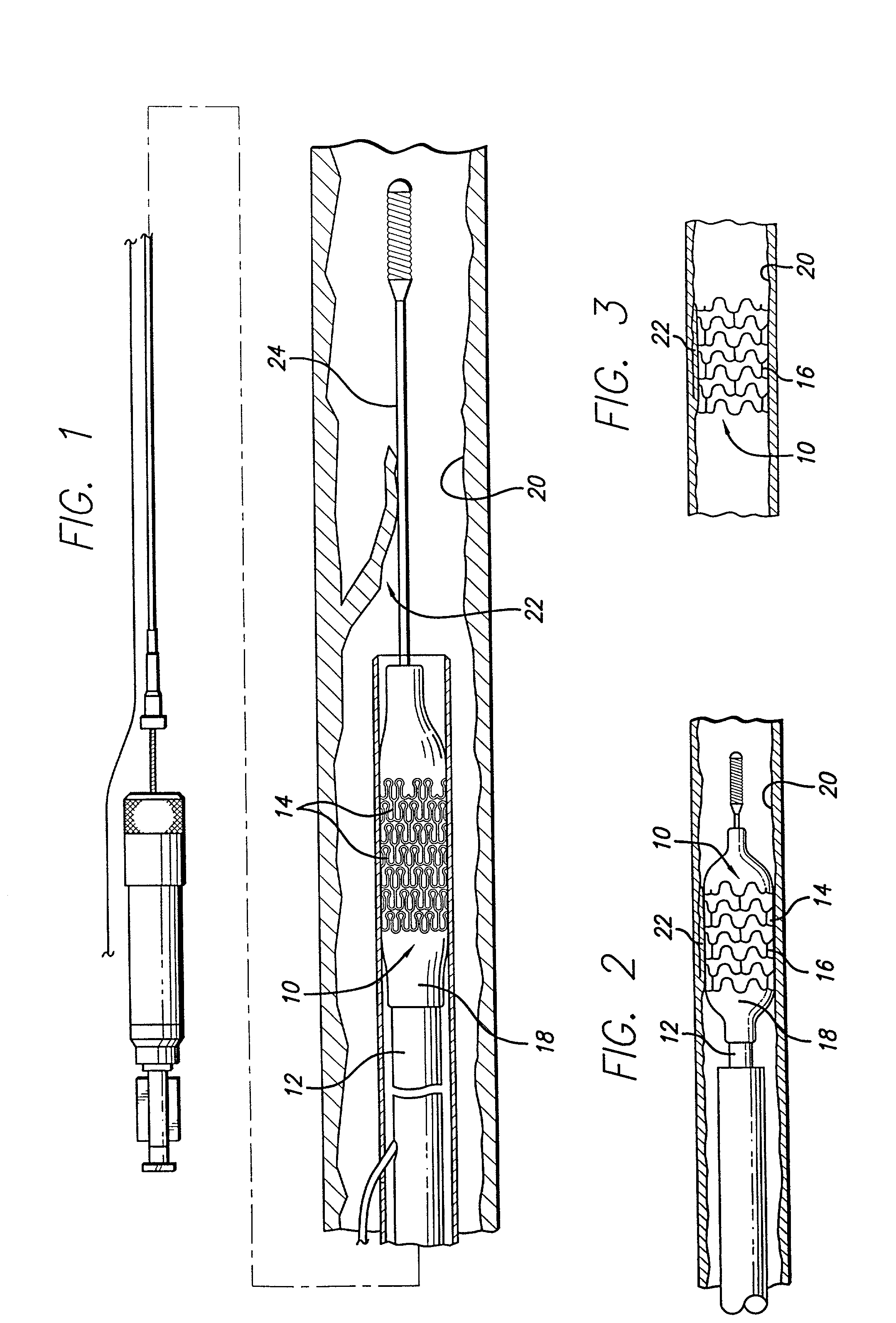
[0032]The present invention is depicted in FIGS. 1–14B for use in various body lumens and procedures, including use in dilated arteries during balloon angioplasties. However, the present invention is not limited to use in blood vessels or angioplasties, but can be used in other body lumens and procedures, including treatment of urinary, digestive, or bile ducts.

[0033]The stent of the preferred embodiment is generally delivered intraluminally using a conventional balloon catheter as is known in the art. The stent is used primarily to ensure the patency of the body lumen in which it is implanted. For example, the stent may be implanted in the coronary arteries after an angioplasty procedure to reinforce the artery against recoil or to tack up a dissection in the arterial wall. The stent is useful for implanting in other body lumens, such as the carotid arteries, illiacs, cerebral vasculature, and other peripheral veins and arteries.

[0034]FIG. 1 illustrates a stent 10, incorporating fe...


PUM


Abstract

An implantable medical device, such as a stent, having roughened areas on an inner surface of the device for enhancing frictional contact between the medical device and a delivery system, such as a balloon catheter to secure the medical device to the delivery system during delivery of the medical device to a body lumen of a patient. Various methods for forming the roughened areas are also provided. The roughened areas may be coated with a material, such as a non-thrombogenic material, to enhance the compatibility of the inner surface of the medical device with fluid flowing through the vessel lumen of the patient.

Description

BACKGROUND OF THE INVENTION[0001]This invention relates to devices for the treatment of heart disease and particularly to endo-arterial prosthesis, which are commonly called stents. More particularly, the invention relates to structures and methods for removably securing the stent to the catheter during delivery through a body lumen.[0002]Several interventional treatment modalities are presently used for heart disease including balloon and laser angioplasty, atherectomy and by-pass surgery. In typical balloon angioplasty procedures, a guiding catheter having a preformed distal tip is percutaneously introduced through the femoral artery into the cardiovascular system of a patient in a conventional Seldinger technique and advanced within the cardiovascular system until the distal tip of the guiding catheter is seated in the ostium. A guidewire is positioned within an inner lumen of a dilatation catheter and then both are advanced through the guiding catheter to the distal end thereof....

Claims


Application Information

Patent Timeline
IPC IPC(8): A61F2/00A61F2/06A61F2/90A61L31/14
CPCA61F2/91A61F2/915A61L31/14A61F2002/30322A61F2002/91508A61F2002/91516A61F2002/91533A61F2002/91575A61F2002/9583A61F2250/0025A61F2250/0026
Inventor HOSSAINY, SYEDMIRZAEE, DARYUSH
Owner ABBOTT CARDIOVASCULAR
Why Eureka
Try Eureka