
Digital signal detector, digital demodulator, method for detecting digital signal, and method for synchronous detecting by digital demodulator

Inactive Publication Date: 2005-12-27
SOCIONEXT INC
View PDF5 Cites 6 Cited by
  • Summary
  • Abstract
  • Description
  • Claims
  • Application Information

AI Technical Summary

Benefits of technology

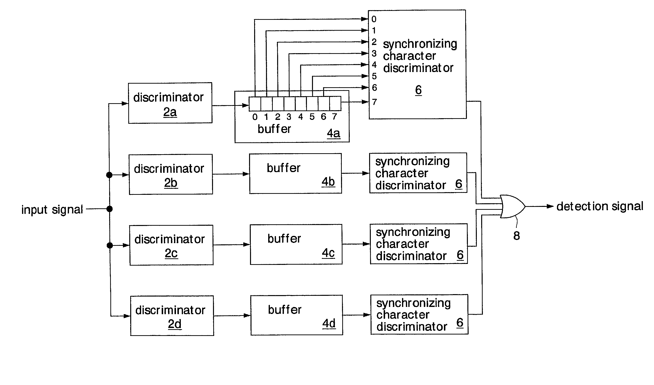
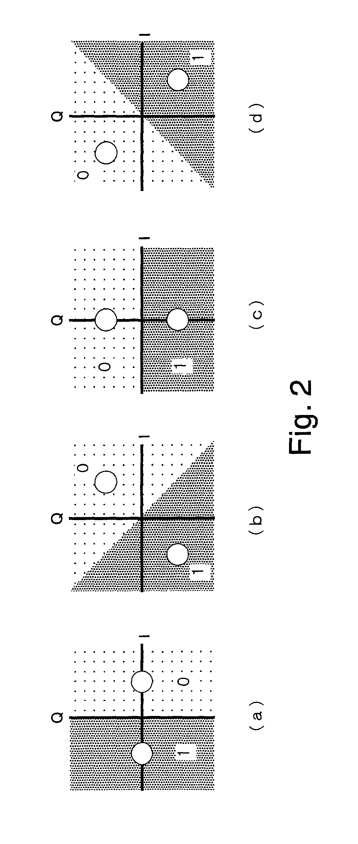
[0023]Generally, in a case where there has a frequency difference between a reference signal used for detecting a digital signal and a carrier wave, it is difficult to detect the predetermined data string. However, when the frequency difference corresponds to a transitional angle of the phase used for discriminating each data in a certain comparison data string, it becomes possible to detect the predetermined data string. A plurality of comparison data strings corresponding to a plurality of differences in frequency are constituted, and the comparison data strings are respectively compared with the expected data string in a plurality of discriminating units so that it is possible to simultaneously detect predetermined data strings with frequency differences from each other. This results in shortening the time required for detection.
[0024]The data composing unit constitutes a plurality of comparison data strings by combining data of the digital data converted by a plurality of conversion units. In other words, since a plurality of conversion units is commonly used to generate a plurality of comparison data strings, an increase in circuit scale is inconsiderable in comparison with the prior art. Utilizing the prior art conversion units can improve design efficiency.
[0026]According to another aspect of a digital modulator and a synchronous detection method for a digital demodulator in the present invention, a demodulator has the above-mentioned digital signal detector. Accordingly, the time required for detection of a predetermined data string and for synchronous detection can be shortened. Since it is possible to simultaneously detect predetermined data strings with frequency differences from each other, the number of times sweeping is performed can be lowered in a digital demodulator where frequencies are swept.
[0027]According to another aspect of a digital demodulator in the present invention, the demodulator has a frequency difference detector. Therefore, a frequency difference between the modulation signal and the reference signal can be detected and the detection result can be fed back to a control system, whereby the time required for synchronous detection can be further shortened.

Problems solved by technology

Generally, in a case where there has a frequency difference between a reference signal used for detecting a digital signal and a carrier wave, it is difficult to detect the predetermined data string.
This results in shortening the time required for detection.
In other words, since a plurality of conversion units is commonly used to generate a plurality of comparison data strings, an increase in circuit scale is inconsiderable in comparison with the prior art.

Method used


Image

  • Digital signal detector, digital demodulator, method for detecting digital signal, and method for synchronous detecting by digital demodulator
  • Digital signal detector, digital demodulator, method for detecting digital signal, and method for synchronous detecting by digital demodulator
  • Digital signal detector, digital demodulator, method for detecting digital signal, and method for synchronous detecting by digital demodulator

Examples


Embodiment Construction

[0043]Hereinafter, a description is given of embodiments of the invention with the accompanying drawings.

[0044]FIG. 6 shows the first embodiment of a digital signal detector, a digital demodulator, and a method for detecting a digital signal, and a method for synchronous detection of the digital demodulator.

[0045]The digital demodulator has an AD converter (to be called hereinafter an “ADC”) 10, a carrier regenerating circuit 12, a decoder 14, a frequency sweeper 16, and a PLL (Phase Locked Loop) 18. The digital demodulator is formed of one chip on a semiconductor substrate as a semiconductor integrated circuit. For example, it is mounted in a receiving terminal (tuner) of the ISDB-S digital broadcast, and carries out quasi-synchronous detection. The carrier regenerating circuit 12 has a synchronizing character detector 20 that is a digital signal detector to detect a synchronizing character, a timing generator 22, a phase detector 24, a loop filter 26, a ROM 28 and, a phase rotator...


PUM


Abstract

A digital signal detector converts quantized modulation signals to digital data according to a plurality of discriminating conditions which are set by shifting phases, which are to be boundaries of discrimination, from each other. Predetermined data in the digital data are combined so that the phases used for discriminating the data rotate in time series, thereby constituting a plurality of comparison data. When a plurality of comparison data strings coincides with expected data strings, predetermined data strings can be detected. Since a plurality of comparison data strings corresponding to a plurality of frequency differences are compared with expected data strings by a plurality of discriminating units, data strings with frequency differences can be simultaneously detected, which results in shortening the time required for detection.

Description

BACKGROUND OF THE INVENTION[0001]1. Field of the Invention[0002]The present invention relates to a digital signal detector that detects a predetermined data string among modulated digital signals and a method for detecting a digital signal. Moreover, the present invention relates to a digital demodulator for demodulating modulated digital signals and a method for synchronous detection by the digital demodulator.[0003]2. Description of the Related Art[0004]Recently, broadcasting systems such as television, etc., has been being shifting from an analog system to a digital system. The ISDB-S (Integrated Services Digital Broadcasting) that is one of the satellite digital broadcasting systems in Japan is a standard for transmitting signals by combinations of a plurality of modulation techniques. It is indispensable that a demodulator of the ISDB-S synchronously detects signals even where the noise field intensity is very high and maintains its synchronized state. In order to enable synchr...

Claims


Application Information

Patent Timeline
IPC IPC(8): H04J3/06H04L7/00H04L27/22H04L7/033H04L7/04H04L27/00H04L27/227
CPCH04L7/042H04L27/2272H04L7/033H04L2027/0034H04L2027/0055H04L2027/0065H04L2027/0095
Inventor YAMAUCHI, KEN
Owner SOCIONEXT INC
Learn More