
System and method for generating microfocused laser-based x-rays for mammography

a laser-based x-ray and microfocus technology, applied in the field of x-ray production, can solve the problems of severe adverse effects, false positive or false negative results of mammography, and unnecessary additional imaging and biopsy

Inactive Publication Date: 2005-12-27
JEAN CLAUDE KLEFER
View PDF21 Cites 4 Cited by
  • Summary
  • Abstract
  • Description
  • Claims
  • Application Information

AI Technical Summary

Benefits of technology

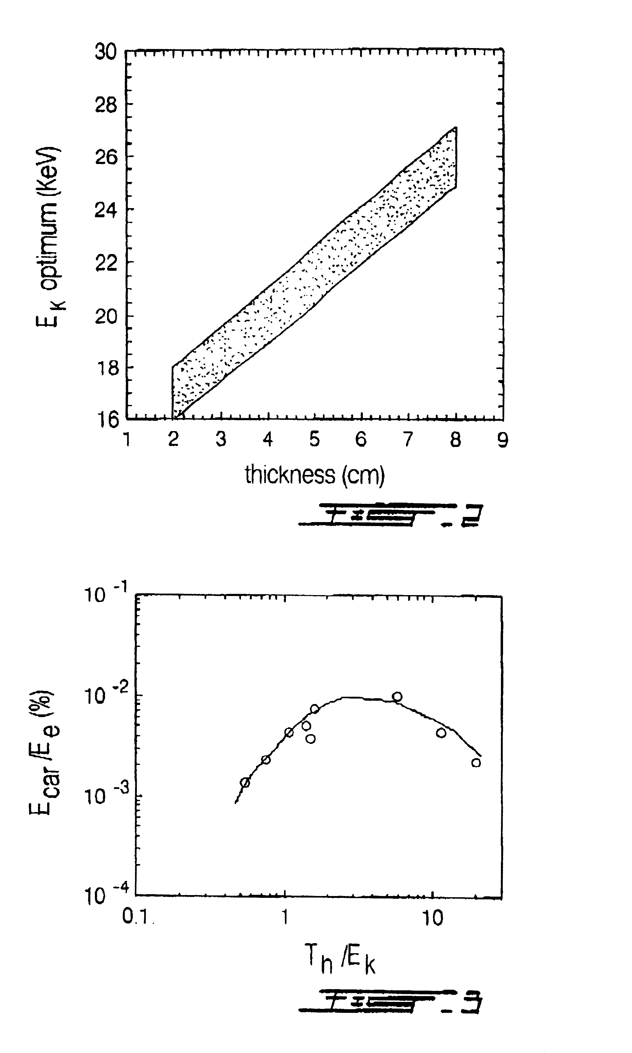
[0021]Specifically an object of the present invention is to provide such method and system allowing optimizing the x-ray source size, its spectral distribution, and the conversion efficiency in the 17.3-28 5 keV range (adapted to the breast thickness and / or density) for improved mammography.
[0024]A system and method according to the present Invention allows producing a very small x-ray source with an x-ray spectrum tailored to a specific patient's breast density and thickness suitable to detect pathology in examined breast, for example microcalcifications, with increased sensitivity and specificity, as compared to method and system from the prior-art.
[0025]Compared to systems and methods from the prior art, a system and method according to the present invention allows to lower calcification detection threshold size down to approximately 30 μm, improves visualization of morphology of microcalcifications and marginal characteristics of masses, improves detection of densities (masses), especially in a dense breast tissue, lowers mean grandular dose, especially in a dense and thick breast tissue, and enhances both sensitivity and specificity of mammography.
[0028]better visualization of pathologies, including demonstration of morphology of very small microcalcifications that cannot be imaged with conventional mammography, that will allow earlier detection of breast cancer with significant benefit for women's health; and
[0032]better imaging of thicker / denser breast due to shorter imaging time. It might completely eliminate “white mammograms” presently obtained with radiopaque breast.

Problems solved by technology

However, still a notable fraction of mammography produces false positive or false negative results These outcomes most occur in the thick and / or dense breast.
False positive results may result in an unnecessary additional imaging and biopsy.
False negative results, which occur sometimes even when a cancer is palpable, have a severe adverse effect due to delayed biopsy and delayed cancer diagnosis.
Some of the inherent limitations of the x-ray tube based screen-film mammography include:relatively large focal spot (typically nominal ˜100 μm);varying effective focal spot size across the imaged breast;suboptimal (below 13 lp / mm) spatial resolution in the upper quadrants for breast thickness above 6 cm:off-focal radiation;a relatively low output (especially with microfocus);a suboptimal spectral characteristic of x-rays for imaging dense fibroglandular tissue and / or thick breast;restricted latitude of film-screen mammography, andrestricted contrast of film-screen mammography.
As a result, only a very limited range of x-ray exposure is acceptable If exposure is too high or too low, it will produce exceedingly high or low optical density thus rendering the image not useful clinically.
While the two last restrictions can be alleviated to a great extent by digital mammography, the other limitations stem from the inherent limitations of x-ray tube and are unlikely to be overcome in the framework of this technology.
However, initially very expensive and large laser systems were required to obtain the required optical power and the LPP x-ray sources were rather large (100 μm-1 mm).
Even though LLP x-ray source created by CPA lasers can be very small (10 μm or less) and bright, with peak power many order of magnitude higher than conventional x-ray tubes, a drawback of CPA laser sources from the prior art has been their low average power However, in recent years, significant progress has been made in this respect 20 W average power CPA lasers are presently available, and a 50 W CPA laser is in the design stage.
However, nobody attempted to simultaneously control the emitted x-ray spectrum, the x-ray source size and conversion efficiency from laser to x-rays.

Method used


Image

  • System and method for generating microfocused laser-based x-rays for mammography
  • System and method for generating microfocused laser-based x-rays for mammography
  • System and method for generating microfocused laser-based x-rays for mammography

Examples


Embodiment Construction

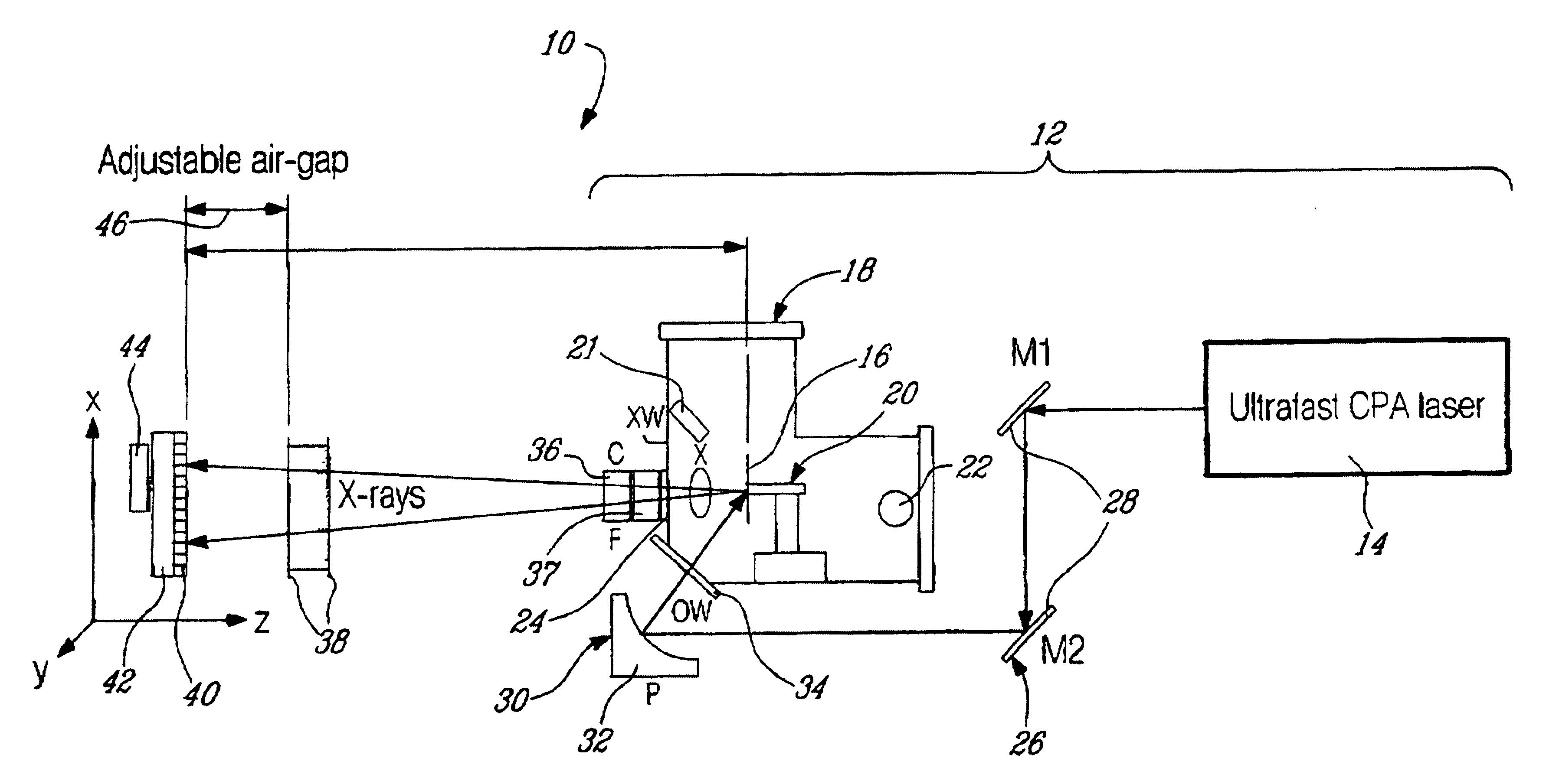
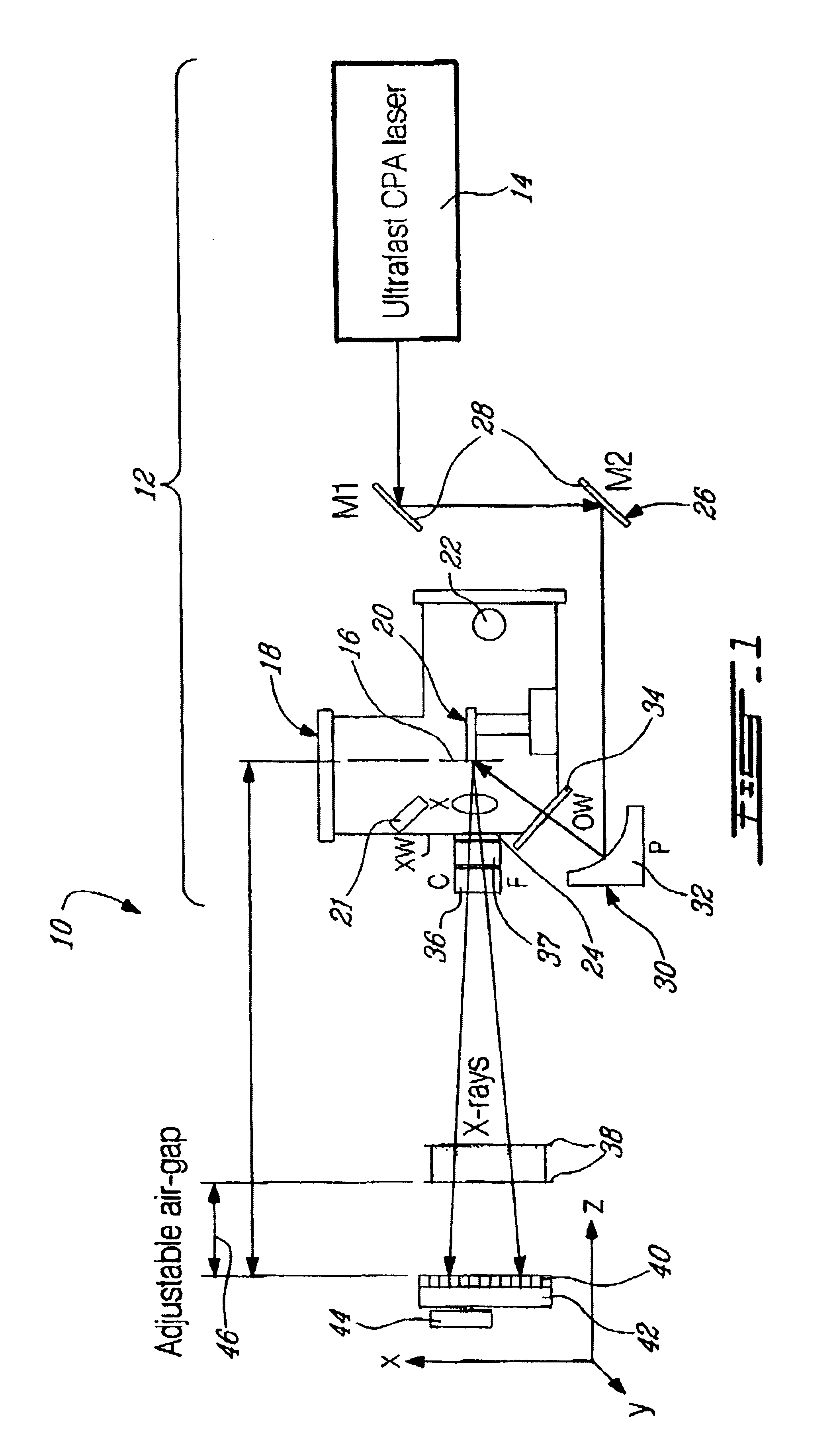
[0041]Turning to FIG. 1, an x-ray mammography system 10 incorporating a system for generating microfocused laser-based x-rays 12 according to embodiments of the present invention are illustrated.

[0042]The x-ray generator 12 is based on both a stationary ultra-fast CPA (chirped-pulse amplified) laser 14 and a solid target 16 with elemental composition so positioned as to be in the focal plane of The laser 14.

[0043]As it will be explained hereinbelow in more detail, the ultra-fast laser 14 and solid target 16 are chosen and configured so that interaction of a laser beam produced by the ultra-fast laser 14 with the solid target 16 produces suprathermal electrons that penetrates the solid target 16 in a spot whose size is comparable to the ultra-fast laser 14 focal spot size. This allows simultaneously optimizing the source size, the x-ray yield and the photon energy.

[0044]The target 16 is mounted in a movable target chamber 18 provided with rapid target / filter changer (not shown), a pr...


PUM


Abstract

The present invention concerns x-ray sources for mammography. A microfocused x-ray source of small size (30 μm and smaller) with x-ray spectrum optimized for enhanced mammography is obtained with a method and system according to the invention. The proposed x-ray source is based on the use of plasmas created by the energy distribution of suprathermal electrons that are produced during the interaction of the laser beam with a solid target. These hot electrons penetrate the surface layer of cold plasma and interact with the solid core of the target. The method and system according to the present invention allows optimizing the x-ray source size, its spectral distribution, and the conversion efficiency in the 17.3-28.5 keV range (adapted to the breast thickness).

Description

FIELD OF THE INVENTION[0001]The present invention relates to x-rays production. More specifically, the present invention is concerned with a method and system for generating microfocused laser-based x-rays suitable for mammographyBACKGROUND OF THE INVENTION[0002]Mammographic signs of early cancer include calcifications, small masses (densities), neo-densities and architectural distortions. Screening mammography aims at revealing these signs and is highly sensitive and specific. However, still a notable fraction of mammography produces false positive or false negative results These outcomes most occur in the thick and / or dense breast. False positive results may result in an unnecessary additional imaging and biopsy. False negative results, which occur sometimes even when a cancer is palpable, have a severe adverse effect due to delayed biopsy and delayed cancer diagnosis.[0003]Presence of calcifications usually helps to detect breast pathology. Although calcifications demonstrate wel...

Claims


Application Information

Patent Timeline
Patent Type & Authority Patents(United States)
IPC IPC(8): A61B6/00H01J35/00H01J35/32H05G2/00
CPCH05G2/001A61B6/502
Inventor KIEFFER, JEAN-CLAUDEKROL, ANDRZEJ
Owner JEAN CLAUDE KLEFER
Learn More