
Data storage apparatus, read data processor, and read data processing method

a data storage and data processing technology, applied in the field of data storage apparatus, can solve the problems of reading data errors, over-correcting conventional methods, and large number of error-occurring bytes, and achieve the effect of improving the probability of error correction

Active Publication Date: 2005-12-27
LENOVO PC INT
View PDF11 Cites 127 Cited by
  • Summary
  • Abstract
  • Description
  • Claims
  • Application Information

AI Technical Summary

Benefits of technology

[0012]The present invention advantageously provides a method for improving the error correcting probability to generate correct read data.
[0015]Because the data storage apparatus of the present invention can compare the pieces of read data with each other, it is possible to decide whether or not an error occurs in the pieces of read data being compared.
[0017]According to the data storage apparatus of the present invention, an error location can be identified accurately by making a comparison among the pieces of read data. When the data storage apparatus is provided with error correcting means that corrects the error in each section decided as unmatching by the comparing means, it is possible to output a piece of read data with extremely high accuracy.
[0021]The read data processor of the present invention identifies error data by deciding that the values are different between the first and second pieces of data in a corresponding position. This identified piece of error data is subjected to an error correction process. Consequently, the error correction probability can be improved.

Problems solved by technology

The read data errors are usually caused by peeling of the magnetic layer from the subject magnetic disk, scratches on the magnetic disk formed by rubbing against the magnetic head, dust and foreign matters stuck on the magnetic disk, etc.
When the number of error-occurred bytes exceeds the error correcting capacity, however, the MPU and / or the HDC (Hard Disk Controller) of the hard disk drive retries reading by changing the read parameters such as the offset in the track width direction of the read head, the coefficient of the channel equalizer, etc.
However, the above conventional method has often been confronted with problems.
For example, error locations are found excessively due to the variation of such characteristics as the soft error rate, etc. among respective heads.
Especially, when random noise is a factor of an uncorrectable error, the error location might be varied each time the data is read therefrom.
In addition, the accuracy of the viterbi decoder to find error locations has often become unstable.
This has also been a problem.

Method used


Image

  • Data storage apparatus, read data processor, and read data processing method
  • Data storage apparatus, read data processor, and read data processing method
  • Data storage apparatus, read data processor, and read data processing method

Examples


Embodiment Construction

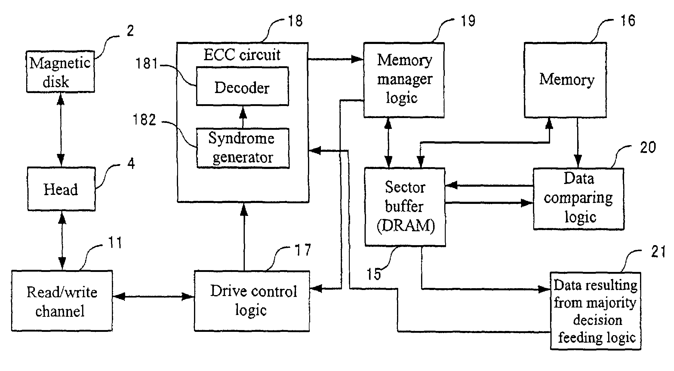
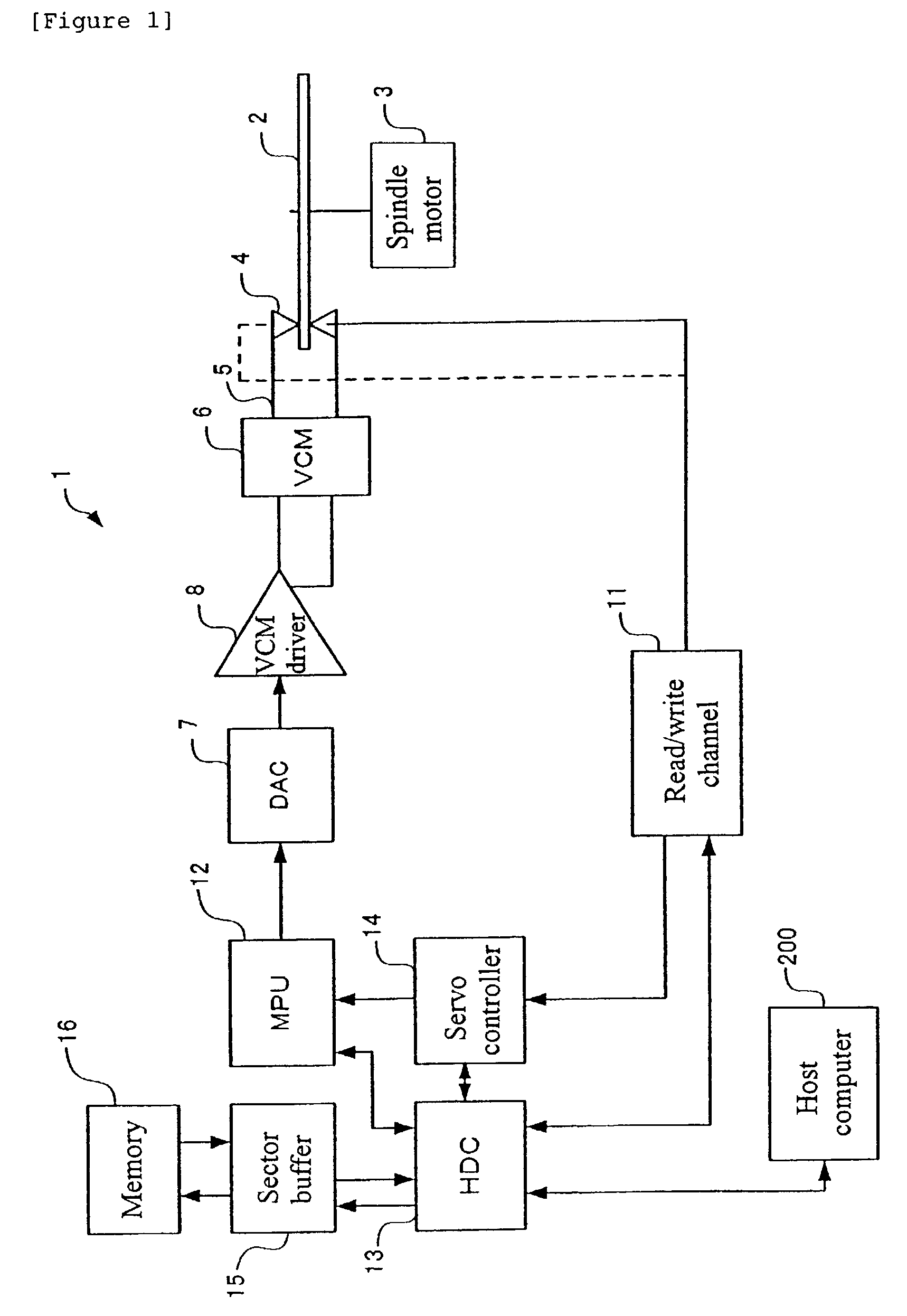
[0055]Hereunder, the present invention will be described in detail with reference to an embodiment of the present invention. FIG. 1 shows a block diagram of the main unit of a hard disk drive 1 in the embodiment of the present invention. The hard disk drive 1 is a data recording / reproducing apparatus in which a head 4 seeks and stays at a predetermined track (position) to write / read data on / from a magnetic disk 2 driven rotationally by a spindle motor 3. In this embodiment, the magnetic disk 2 is assumed to be single while a plurality of disks 2 may be provided as needed.

[0056]The magnetic disk 2 is driven rotationally around the spindle shaft of the spindle motor 3 while the hard disk drive 1 is in operation. When the hard disk drive 1 is not in operation, the magnetic disk 2 does not rotate. On the surface of the magnetic disk 2 are formed a plurality of location information (servo information) storing fields in the radial direction of the magnetic disk 2. Data is stored in other ...


PUM


Abstract

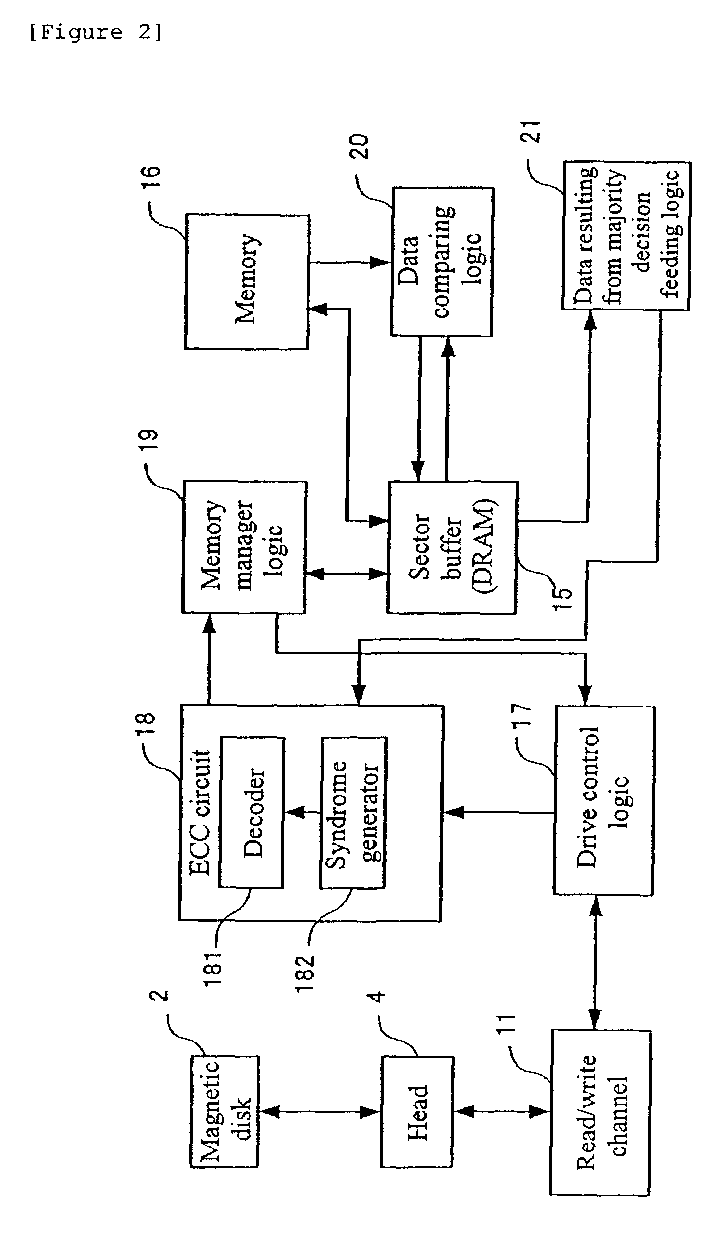
To improve the probability of error correction, thereby generating correct read data. Data is read from the same sector by a number of times and a majority decision is done in the same address, thereby the most frequently read value is regarded as the true data value in the address. For example, for an address 00, “00” is handled as a true data value.

Description

BACKGROUND OF THE INVENTION[0001]1. Field of the Invention[0002]The present invention relates to a data storage apparatus as a hard disk drive. More particularly, the present invention relates to a method for deciding whether or not an error has occurred in each data read from a data storage medium and further a method employed for error data correction.[0003]2. Background Art[0004]A hard disk drive is one of the most popular external storage apparatuses employed for computers. As known well, a magnetic disk, which is a storage medium of such a hard disk drive, consists of sectors (the minimum unit of recording) formed by radially partitioning tracks on the surface of the disk. The tracks are formed by dividing the surface of the disk just like the growth rings. The line recording density of such the magnetic disk can be increased as closing to the outer periphery. This is why the “zoned bit recording” method, which is the present mainstream of data recording methods of magnetic dis...

Claims


Application Information

Patent Timeline
IPC IPC(8): G06F11/08G06F3/06G11B20/10G11B20/18H03M13/43
CPCG11B20/1809
Inventor FUKUSHIMA, YUKIOKATOH, KATSUHIKOKOBAYASHI, SHUNSUKEKURODA, TAKASHINAKAGAWA, YUZOSAI, FUMINORISHIMONO, EMITAMURA, TETSUYAUEDA, TETSUO
Owner LENOVO PC INT
Learn More