

Single-frequency narrow linewidth 1mum fiber laser
a fiber laser and single-frequency technology, applied in the field of fiber lasers, can solve the problems of difficult if not impossible to demonstrate high, current 1 m fiber laser technology does not support such performance, etc., and achieves the effects of facilitating splicing, and reducing the number of splicing
Active Publication Date: 2006-01-03
NP PHOTONICS A CORP OF DELAWARE
View PDF8 Cites 24 Cited by
- Summary
- Abstract
- Description
- Claims
- Application Information
AI Technical Summary
Benefits of technology
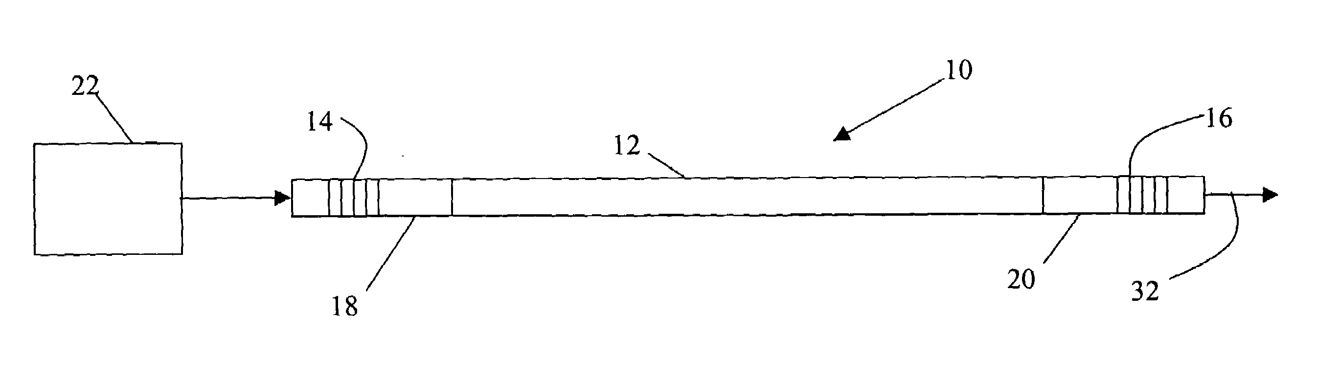
[0011]The 1 um fiber laser is formed with an oxide-based multi-component glass fiber doped with triply ionized rare-earth ytterbium ions and fiber gratings formed in sections of passive silica fiber and fused thereto. The multi-component glass supports higher doping concentrations, 0.5–30 wt. %, than silica fiber, hence higher output power levels in fiber lengths less than 5 cm and preferably less than 3 cm. Formation of the gratings in passive silica fiber both facilitates splicing to other optical components and reduces noise thus improving linewidth. The use of a polarization maintaining (PM) fiber in the pump source further improves wavelength stability, linewidth and vibration / acoustic sensitivity.
[0012]In another embodiment, the gain fiber is a polarization maintaining (PM) fiber, which reduces the noise level in the laser and improves output power stability. As a result of their specific local environment, the active ions experience an anisotropy that leads to polarization dependent gain, which means that the gain spectra for two different polarization components are not the same. Combining polarization selective feedback with a polarization maintaining active fiber reduces the low frequency noise that results from random polarization fluctuations inside the laser cavity.
Problems solved by technology
Current 1 μm fiber laser technology does not support such performance.
It is very difficult if not impossible to demonstrate high power single frequency narrow linewidth 1 μm ytterbium silica fiber laser with the present state of the art.
Method used
View moreImage
Smart ImageViewing Examples

Examples
example 1
[0030]
No. 1P2O5Al2O3La2O3Yb2O3BaOB2O3ZnOTotalWt %63.304.330.312.0027.681.231.15100.00
example 2
[0031]
No. 2P2O5Al2O3La2O3Yb2O3BaOB2O3ZnOTotalWt %61.054.170.005.7926.691.191.11100.00
example 3
[0032]
No. 3P2O5Al2O3La2O3Yb2O3BaOB2O3ZnOTotalWt %59.624.070.008.0026.061.161.0899.99
Login to View More PUM
 Abstract
A compact single frequency, single-mode 1 μm fiber laser with narrow linewidth (<10 kHz) and high output power (>2 mW) is formed with an oxide-based multi-component glass fiber doped with triply ionized rare-earth ytterbium ions and fiber gratings formed in sections of passive silica fiber and fused thereto. The multi-component glass supports higher doping concentrations than standard silica fiber, hence higher output power levels in short cavities. Formation of the gratings in passive silica fiber both facilitates splicing to other optical components and reduces noise thus improving linewidth.
Description
BACKGROUND OF THE INVENTION[0001]1. Field of the Invention[0002]This invention relates to fiber lasers and more specifically to a single frequency 1 μm fiber laser with narrow linewidth (<10 kHz) formed from ytterbium doped oxide-based multicomponent glasses.[0003]2. Description of the Related Art[0004]Rare-earth doped glass fiber lasers were first proposed in the 1960s and have received considerable attention in the 1980s for potential applications in optical communication (Michel J. F. Digonnet, “Rare-Earth Doped Fiber Lasers and Amplifiers,” Marcel Dekker, New York 2001). For laser emission to occur, the active fiber is placed inside a resonant cavity. The optical feedback can be provided simply by the reflectivity of the end facets, by mirrors, by distributed feedback Bragg (DFB) gratings, or by distributed Bragg reflectors (DBR), or by constructing a ring cavity structure. Laser emission occurs when the total gain overcomes the losses in the cavity. Hence, a minimum gain has...
Claims
Login to View More Application Information
Patent Timeline
 IPC IPC(8): H01S3/30H01S3/08H01S3/00
CPCH01S3/06716H01S3/17H01S3/09415G02B6/0218H01S3/06704H01S3/08031H01S3/175H01S3/1055H01S3/1618
InventorJIANG, SHIBINKANEDA, YUSHISPEIGELBERG, CHRISTINELUO, TAO
OwnerNP PHOTONICS A CORP OF DELAWARE