Carrier restoration apparatus and method

a carrier and restoration technology, applied in the field of carrier restoration apparatus and method, can solve the problems of increasing the cost of preparing the tuner, and increasing the effect of noise amplified to its square value, so as to improve the frequency acquisition performance and phase tracking performan

Inactive Publication Date: 2006-01-03
LG ELECTRONICS INC
View PDF11 Cites 17 Cited by
  • Summary
  • Abstract
  • Description
  • Claims
  • Application Information

AI Technical Summary

Benefits of technology

[0041]An object of the present invention is to provide a carrier restoration apparatus and method which can improve the frequency acquisition performance and the phase tracking performance by separately constructing a loop for frequency acquisition and a loop for phase tracking.

Problems solved by technology

As described above, in case of the QAM, the phase error of the restored carrier has an effect on not only the gain error but also the error due to the interference, and thus this causes its effect to become more serious.
The above-described Costas loop method has the problem in that as the error signal is multiplied by the noise, the noise is amplified to its square value.
First, since an elaborate high-quality tuner should be used according to a small acquisition / tracking range, the cost for preparing the tuner is increased. That is, a tuner with a small frequency offset and small phase jitter during the carrier restoration has a good performance, and such a tuner having the good performance is typically expensive.
Second, the BER performance of the receiver is lowered due to a large residual phase jitter.
Third, the acquisition / tracking performance with respect to a small input SNR deteriorates. That is because if the receiving power (i.e., SNR) of the input signal is small, the error detection section of the conventional carrier restoration section produces an inaccurate error.
Fourth, the acquisition / tracking performance with respect to the ISI / ghost channel deteriorates widely. Even in the channel having a strong ISI / ghost, the error detection section also produces an inaccurate error in the same manner.

Method used


Image

  • Carrier restoration apparatus and method
  • Carrier restoration apparatus and method
  • Carrier restoration apparatus and method

Examples


Embodiment Construction

[0067]Reference will now be made in detail to the preferred embodiments of the present invention, examples of which are illustrated in the accompanying drawings.

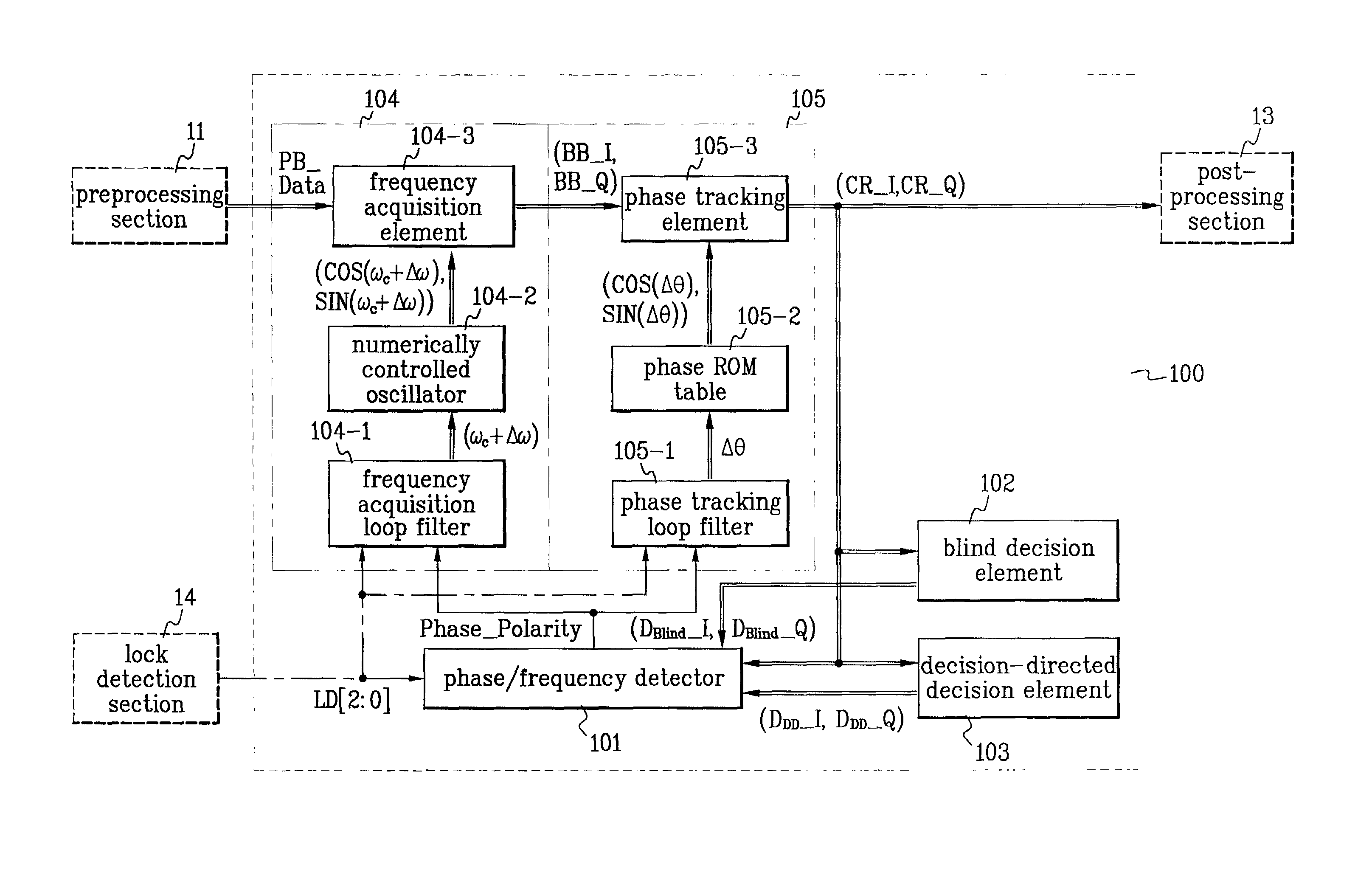
[0068]FIG. 5 is a block diagram illustrating the construction of a carrier restoration apparatus according to the present invention applied to a TV receiver. Referring to FIG. 5, a carrier restoration section 100 includes a PLL section 104 for frequency acquisition, a PLL section 105 for phase tracking, and a phase / frequency detector 101 used in common for the different PLL section 104 for frequency acquisition and PLL section 105 for phase tracking.

[0069]Also, the carrier restoration section 100 includes a blind decision element 102 and a decision-directed decision element 103 for determining the kind of decision signal constellations from an output of the PLL section for phase tracking, and operating the phase / frequency detector 101 in a blind mode or decision-directed mode.

[0070]A lock detection section 14 determines an o...


PUM


Abstract

A carrier restoration apparatus for acquiring a frequency offset and tracking a phase jitter from a pass-band digital signal having the frequency offset and the phase jitter is disclosed. In the apparatus, a frequency acquisition PLL section for acquiring the frequency offset and a phase tracking PLL section for tracking the residual phase jitter are separately constructed, and the apparatus operates in two modes for first acquiring the frequency offset and then tracking the residual phase jitter. Thus, a rapid acquisition / tracking is performed so as to minimize the frequency offset and phase jitter of several hundred KHz produced from a tuner or an RF oscillator, and a high-reliability acquisition / tracking can be performed even under the low SNR and serious channel ISI (i.e., ghost).

Description

BACKGROUND OF THE INVENTION[0001]1. Field of the Invention[0002]The present invention relates generally to a quadrature amplitude modulation / phase shift keying (QAM / PSK) receiver, and more particularly, to a carrier restoration apparatus and method that compensates for a frequency offset and a phase jitter of a carrier.[0003]2. Background of the Related Art[0004]Typically, a quadrature amplitude modulation (QAM) is used for cable transmission / reception of compressed digital video data in a HDTV. Especially, the 256 QAM modulation is performed in a manner that the compressed video data is encoded for transmission to output 256 constellations corresponding to 8 bits per symbol period (i.e., 5.3607 MHz) as vector values, orthogonal projected values of the vector values on orthogonal axes I and Q are carrier-suppression-modulated by sine and cosine waves, respectively, and then the modulated waves are added together to be transmitted.[0005]In order for a receiving end to obtain the vect...

Claims


Application Information

Patent Timeline
Patent Type & Authority Patents(United States)
IPC IPC(8): H04L27/38H04B1/10H04N7/015H04L27/00H04L27/227
CPCH04L27/2273H04L2027/003H04L2027/0067H04L2027/0065H04L2027/0057H04N7/015
Inventor AHN, KEUN HEE
Owner LG ELECTRONICS INC
Why Eureka
Try Eureka