

Optical fiber and optical transmission system using such optical fiber
a technology of optical transmission system and optical fiber, which is applied in the direction of optical fiber with multi-layer core/cladding, optical waveguide light guide, instruments, etc., can solve the problems of large optical transmission hurdle, nonlinear phenomenon such as spm or xpm doesn't appear easily, and new wave distortion of signal light. achieve the effect of increasing capacity
- Summary
- Abstract
- Description
- Claims
- Application Information
AI Technical Summary
Benefits of technology
Problems solved by technology
Method used
Image

Examples
examples 1 to 3
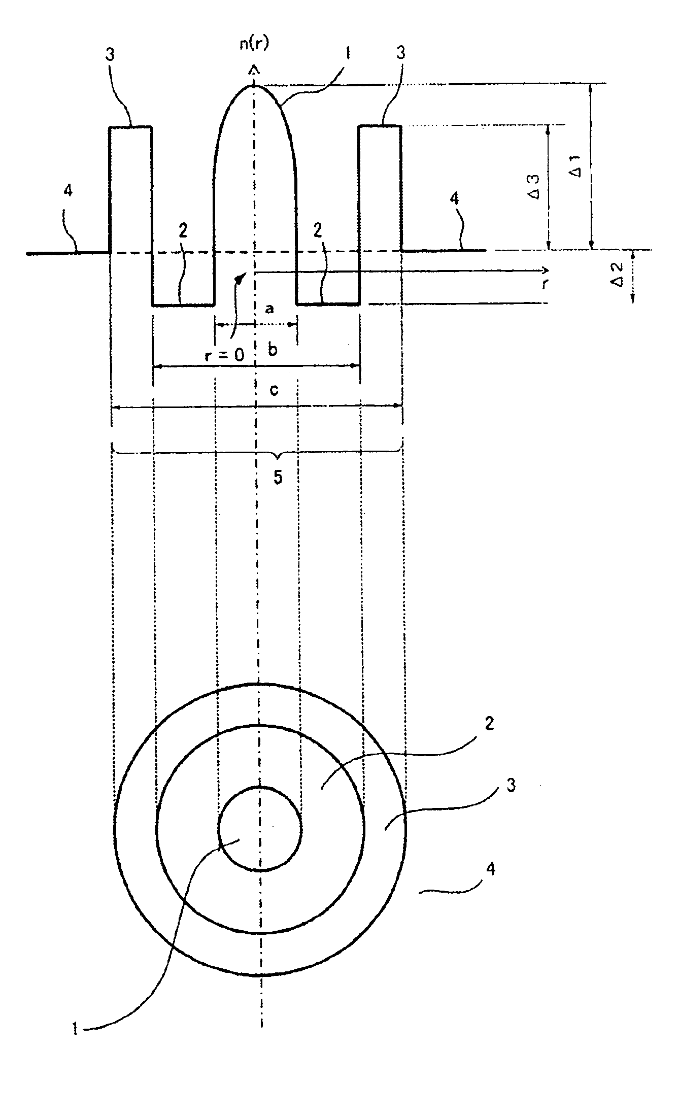
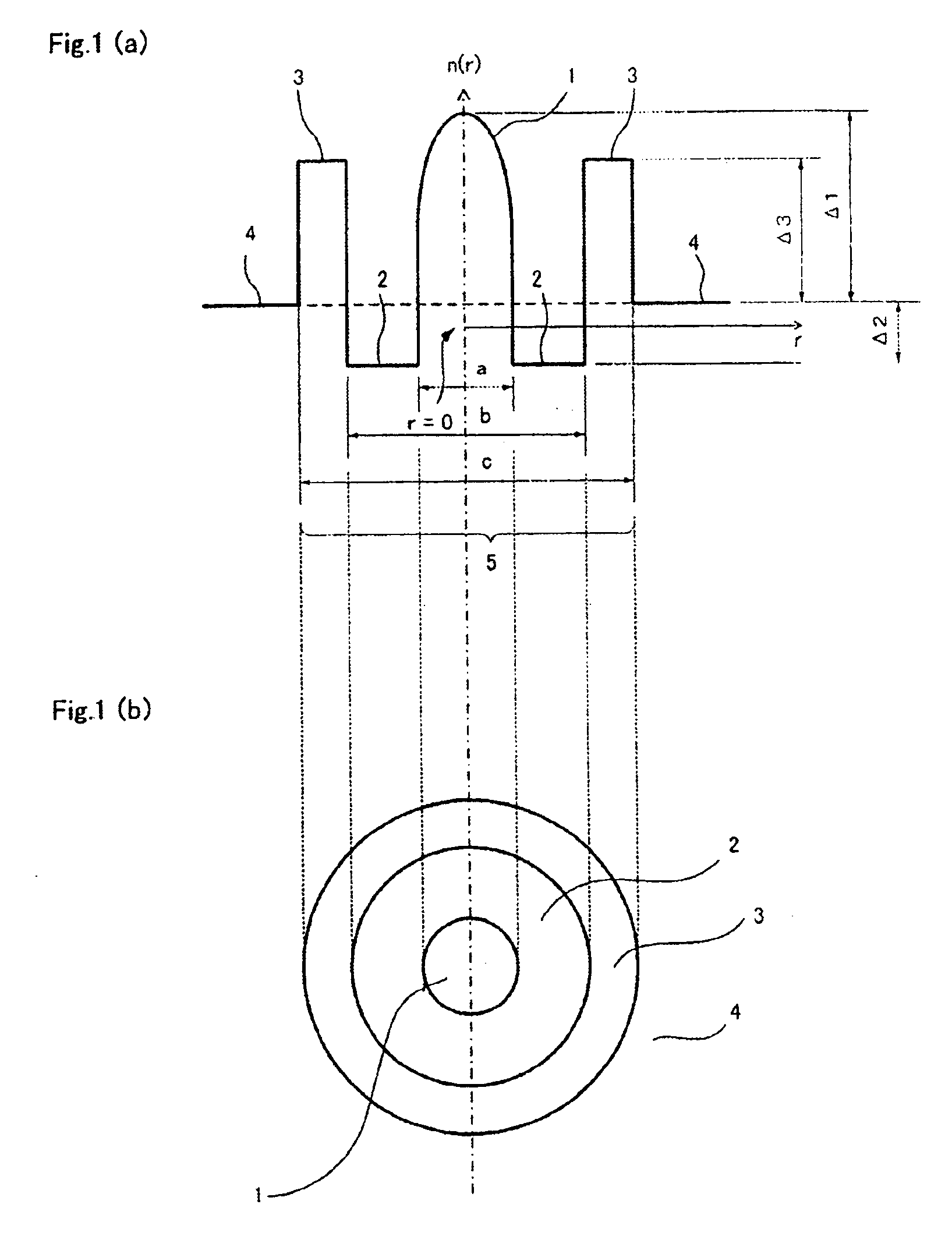
(Optical Fiber A)
[0098]Optical fiber A shown in FIG. 1 were manufactured. The manufacturing target assumed were that of example 1 to 3 of Table 3, and almost the same refractive index profile as the target were obtained. Table 6 shows the characteristic of these optical fibers. All the measurement wavelength of each characteristic was set to 1550 nm.
[0099]
TABLE 6Reflective Index ProfileCharacteristicsCoreDispersionBendingΔ1Δ2Δ3DiameterLossDispersionSlopeAeffLoss*λcPMD%α%%Ra1Ra2μmdB / kmps / nm / kmps / nm2 / kmμm2dB / mnmps / km1 / 2Sample 10.506−0.150.520.320.6210.90.19615.50.0711585.415680.06Sample 20.476−0.150.520.280.6010.70.19614.30.0721524.515750.05Sample 30.508−0.100.500.280.6010.60.19216.10.0691494.315490.05*Bending Loss; in a diameter of 20 mm
[0100]As clear from Table 6, Aeff of the optical fiber of example 1 to 3 are all 130 μm2 or more, and a wave distortion caused by nonlinear phenomena such as SPM and XPM can be adequately suppressed. Moreover, since the dispersion is also smaller tha...
examples 5 to 7
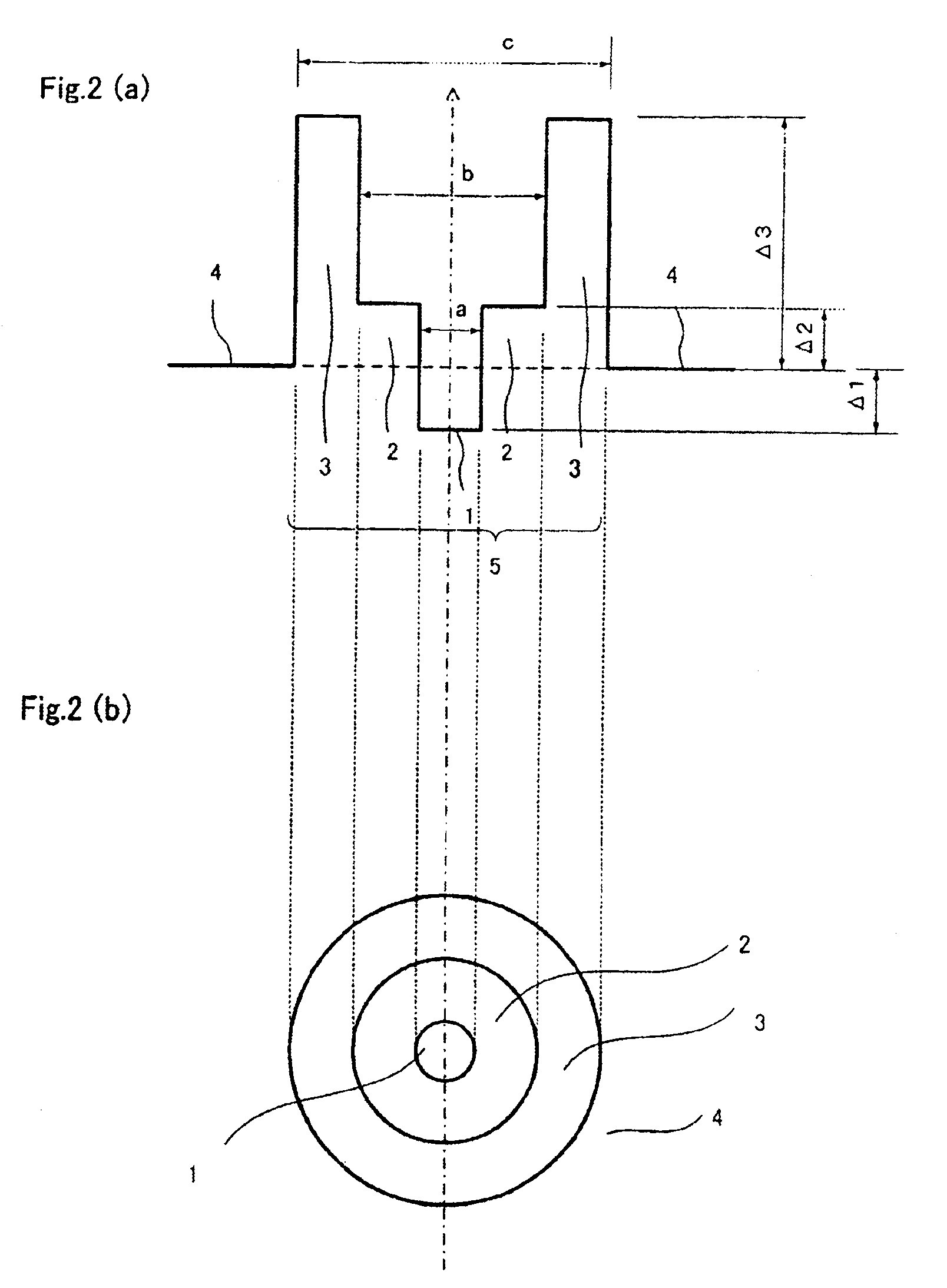
(Optical Fiber B)
[0103]In the same way, Optical fiber B shown in FIG. 2 was manufactured. The manufacturing target assumed were that of example 5 to 7 of Table 5, and almost the same refractive index profile as the target were obtained. Table 7 shows the characteristic of these optical fibers. All the measurement wavelength of each characteristic was set to 1550 nm.
[0104]
TABLE 7Reflective Index ProfileCharacteristicsCoreDispersionBendingΔ1Δ2Δ3DiameterLossDispersionSlopeAeffLoss*λcPMD%%%Ra1Ra2μmdB / kmps / nm / kmps / nm2 / kmμm2dB / mnmps / km1 / 2Sample 5−0.400.100.600.360.659.80.23511.50.0721405.915680.08Sample 6−0.300.100.600.400.6310.20.22611.30.0741445.515880.06Sample 7−0.800.150.600.410.649.90.2389.00.0721456.115910.08*Bending Loss; in a diameter of 20 mm
[0105]As clear from Table 7, all optical fibers of examples 5 to 7 have the Aeff of 130 μm2 or more, similar to examples 1 to 3.
[0106]Moreover, because the dispersion has become further smaller compared with the optical fiber of example 1 to...
example
(Optical Transmission System)
[0109]Some embodiments of the optical transmission system of the present invention are explained by using the drawing as follows.
[0110]A nonlinear phenomenon appears remarkably in general in the part where optical power is strong. Therefore, in the optical transmission system, the method of arranging the Large Aeff SMF just behind an optical amplifier, to control a nonlinear phenomenon of DCF or IDF, followed by the DCF or IDF is generally employed.
[0111]FIG. 5 is a schematic sectional view that shows the optical transmission system of an embodiment according to the present invention, and an example that the optical fiber of the present invention is used as a transmission line and the dispersion is compensated by DCF in the module form.
[0112]The signal input from Transmitter 11 is amplified with amplifier 12, and transmitted with optical fiber 13 of the present invention. Afterwards, the dispersion is compensated by DCF14 in the module form, and it is re...
PUM
 Abstract
Description
Claims
Application Information