Compressor stator vane

a technology of compressor and casing, which is applied in the direction of stators, machines/engines, liquid fuel engines, etc., can solve the problems of small pressure fluctuations in the vanes, loose vanes, relative motion between the vane base and the vane base, etc., to avoid the wear of the vane base and reduce chatter

Inactive Publication Date: 2006-01-10
DRS NAVAL POWER SYST INC
View PDF23 Cites 69 Cited by
  • Summary
  • Abstract
  • Description
  • Claims
  • Application Information

AI Technical Summary

Benefits of technology

[0023]The invention is a means for modifying a set of compressor stator vanes for an industrial gas turbine so as to avoid wear of the vane base and reduce chatter. The vanes are joined by a simple mechanical means such that the discrete vanes form a rigid ring of vanes

Problems solved by technology

In addition, the vanes are subject to small pressure fluctuations during operation.
These result in relative motion between the vane base and the casing in which the vanes are assembled.
The relative motion results in wear of both the vane base and casing, which, in turn, results in loo

Method used


Image

  • Compressor stator vane
  • Compressor stator vane
  • Compressor stator vane

Examples


Embodiment Construction

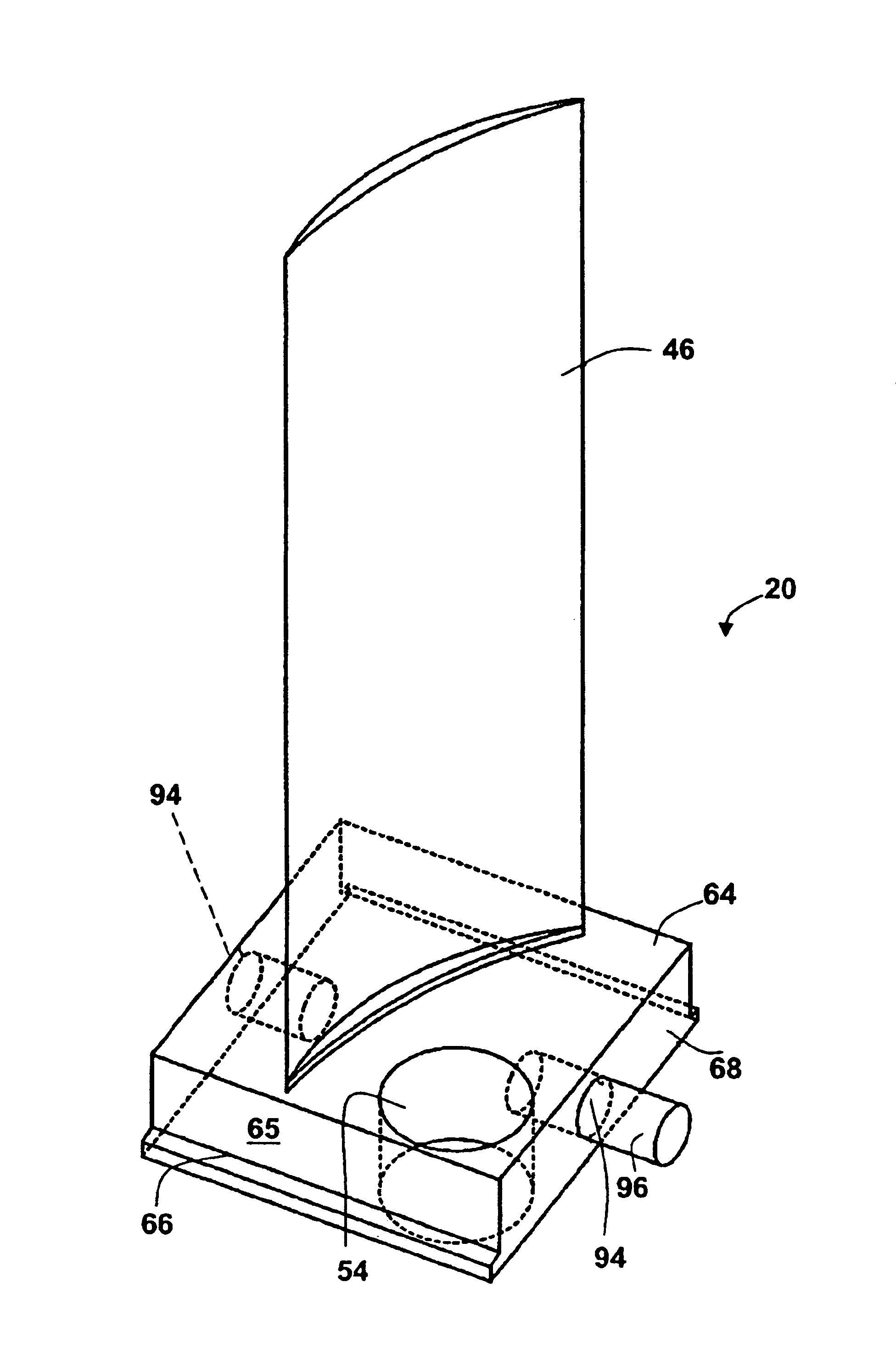
[0055]Referring to the drawings in detail, where like numerals indicate like elements, there is illustrated a vane system including a vane unit in accordance with the present invention designated generally as 20.

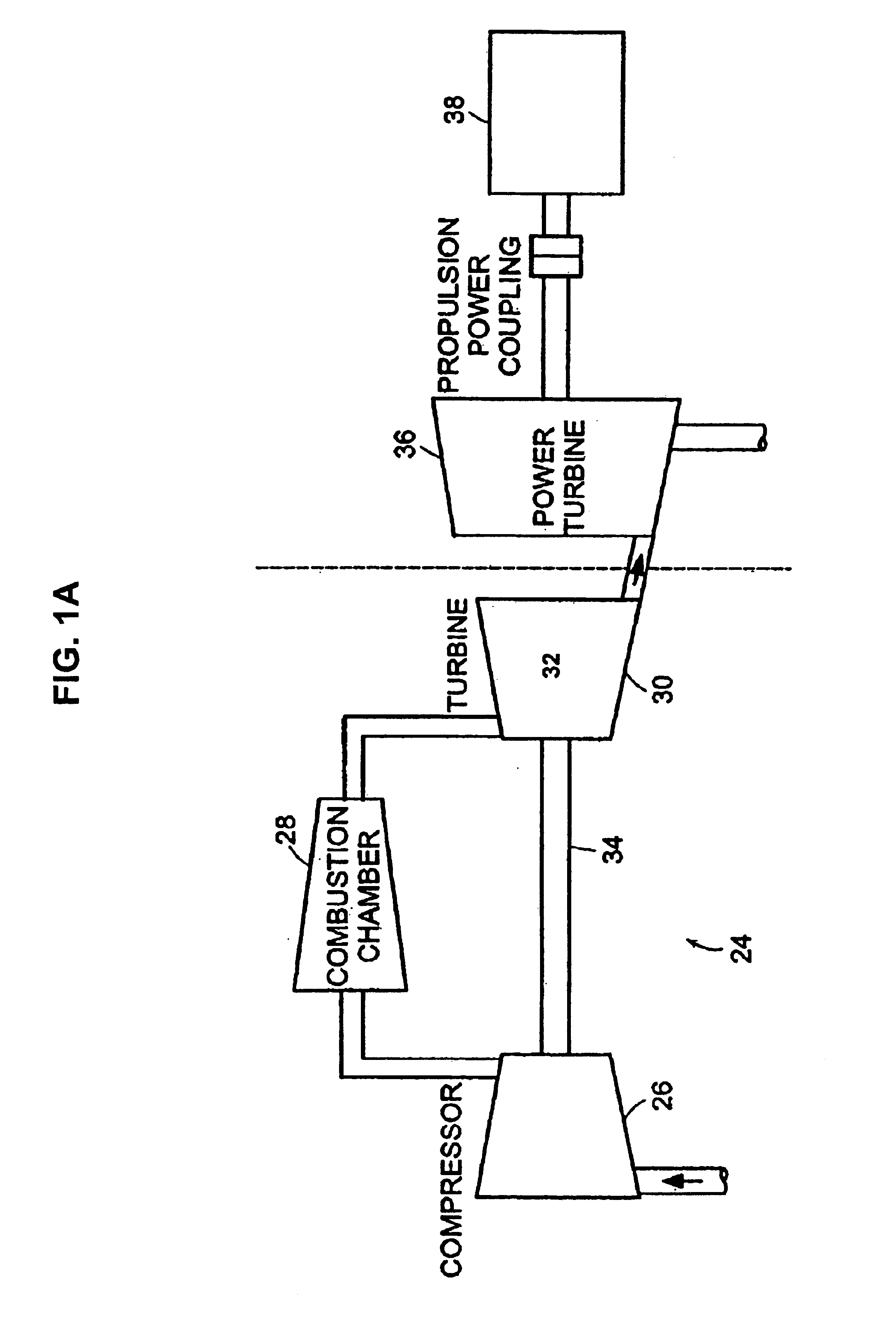
[0056]Gas turbines are used in various locations such as aircraft, ships, and in power plants. Referring to FIG. 1A a schematic of a gas turbine 24 is shown. The turbine 24 has a compressor section 26 that compresses atmospheric air prior to the air being mixed and combusted with a fuel, i.e., gas, in a combustion chamber 28.

[0057]The turbine 24 has a turbine section 30 that converts the energy of the compressed heated air to rotation energy. The turbine section 30 is tailored differently depending on the purpose of the turbine. In a power plant scenario, the turbine section 30 of the gas turbine 24 has two portions. One portion 32 drives a shaft 34 to the compressor section 26 and the second portion is a power turbine 36 for driving a generator 38.

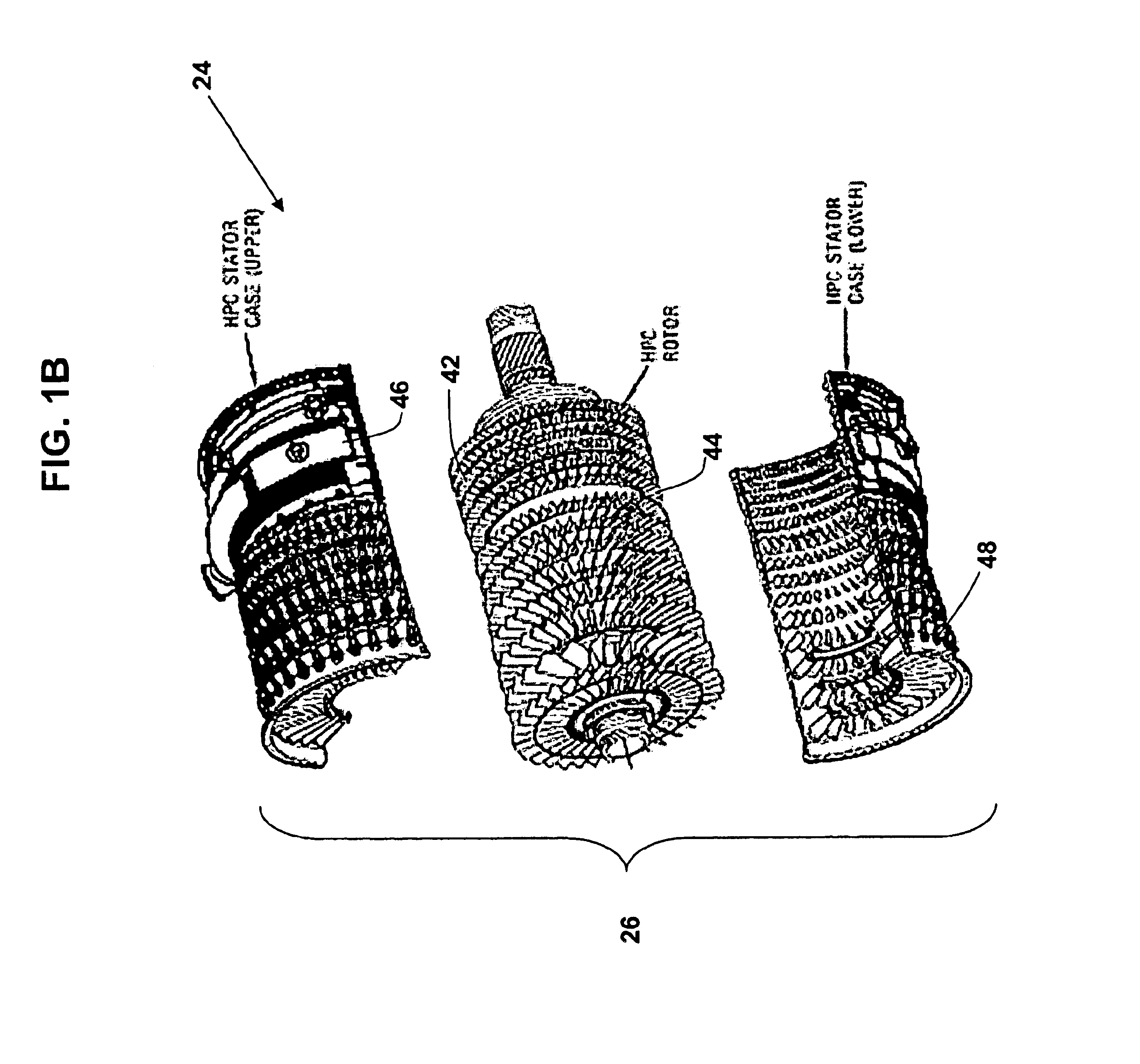
[0058]Referring to FIG. 1B...


PUM


Abstract

A vane unit system having a plurality of vane units having at least one air foil projecting from a base. The base has a hole which receives a pin which extends between adjacent bases of vane units therein forming a rigid ring of vanes that are less susceptible to vane motion caused by pressure fluctuations within the compressor of a gas turbine. A blade assembly tool having a shape to fit within the slot in a casing that receives the vane units allows for the installation of vane units with interlocking pins without the necessity of having to remove the rotor from the casing.

Description

CROSS REFERENCES TO RELATED APPLICATIONS[0001]This application claims the benefit of U.S. Provisional Application No. 60 / 358,931 filed Feb. 22, 2002, the contents of which are incorporated herein by reference in their entirety.BACKGROUND OF THE INVENTION[0002]Compressor stator vanes in an industrial gas turbine are loaded and unloaded during start-stop cycles. In addition, the vanes are subject to small pressure fluctuations during operation. These result in relative motion between the vane base and the casing in which the vanes are assembled. The relative motion results in wear of both the vane base and casing, which, in turn, results in loose vanes. An example of the wear pattern on the base of a vane unit and in particular on a projection on the contact surface is shown in FIGS. 17A and 17B. The loose vanes become more susceptible to relative motion and begin to chatter. Expensive repair or replacement of the vanes and case does not solve the wear and chatter problem; it simply b...

Claims


Application Information

Patent Timeline
IPC IPC(8): F01D1/02F01D5/22
CPCF01D5/22F01D9/042F05D2230/70F05D2230/60Y02T50/673Y02T50/60
Inventor ANDERSON, RODGER O.WILLETT, FRED T.
Owner DRS NAVAL POWER SYST INC
Why Eureka
Try Eureka