Packet lockstep system and method

a lockstep and data packet technology, applied in the field of data transmission, can solve the problems of increased network traffic and potential bottlenecks surrounding the nas server and storage device, performance, and latency and bandwidth, and achieve the effect of reducing overhead processing, enhancing reliable data packet throughput, and reducing overhead processing

Active Publication Date: 2006-01-10
AVAGO TECH INT SALES PTE LTD
View PDF5 Cites 51 Cited by
  • Summary
  • Abstract
  • Description
  • Claims
  • Application Information

AI Technical Summary

Benefits of technology

[0029]Implementations of the present invention can be beneficial to any packet-switched system or network that is intended to provide a fault tolerant RAS (Reliability, Availability, Serviceability) architecture and strategy, in addition to the unified network system described herein, and can enhance reliable data packet throughput. The present invention is configurable, for example, in a redundant system that is intended to avoid single-point failures at any system component. Lockstepping at the data packet level is less dependent on the system transaction order on common buses or memory, which are typically difficult to control given the unpredictability inherent to circuit cards / components. Packet lockstepping offers a method for analyzing data throughput on a flow-by-flow basis instead of depending on card / component transaction level events.
[0030]The present invention is also beneficial in that the intermediate sources perform less overhead processing related to fault tolerance compared with components that use the aforementioned “heartbeat” scheme because the intermediate sources are not required to send, receive, and manage the “heartbeat” messages. Additionally, a separate component performs the data integrity verification function in lieu of the intermediate sources, further reducing the overhead processing. Further still, the present invention does not require complete and independent redundant system data paths, but can be implemented in various different locations within a system, and can be used to monitor various components operating in lockstep.

Problems solved by technology

A shortcoming of a DAS system is that when the server is off-line or not functioning properly, its storage capability and its associated files are unavailable.
A NAS system typically shares the Local Area Network (LAN) bandwidth, therefore a disadvantage of a NAS system is the increased network traffic and potential bottlenecks surrounding the NAS server and storage devices.
The deployment of prior SAN technologies in the growing enterprise-class computing and storage environment has created several challenges.
One such challenge is to provide a scalable system in which thousands of storage devices can be interconnected.
Performance (e.g., latency and bandwidth) and reliability decline in such systems.
Additionally, systems including hundreds of interconnected switches are inherently difficult to manage and to diagnose for faults, both from hardware and software perspectives.
Further still, since no SAN protocol is truly ubiquitous enough to be readily integrated with other networking architectures in a heterogeneous SAN environment, bridges and conversion equipment are required, increasing the costs to build and maintain such a system.
Another such challenge is to provide a system that is fault tolerant.
To this end, a hardware fault is typically detected and circumvented by switching to a redundant component.
However, if the transactions are not identical an exception handler typically identifies the faulty processing set.
Such schemes can be unpredictable as a result of component or card unpredictability.
For example, small variations in the temperatures of identical components in identical processors running in parallel can trigger processor interrupts differently, causing the parallel processors to fall out of lockstep.
Klug et al. teach that asynchronous inputs to redundant processors will generally fail in a clock lockstep mode.
According to Klug et al., an asynchronous input signal can change during a sampling time, and there is a certain probability that the change will only be seen by one of the two processors, thus a comparison between the two processors would show a discrepancy, or failure, even though both processors were functioning properly.
Circuit board lockstepping schemes are similarly problematic.
For example, unpredictable minute variations between circuit boards operating in parallel make it difficult to maintain a lockstep relationship between them.
Lockstepping at the data packet level is less dependent on the system transaction order on common buses or memory, which are typically difficult to control given the unpredictability inherent to circuit cards / components.

Method used


Image

  • Packet lockstep system and method
  • Packet lockstep system and method
  • Packet lockstep system and method

Examples


Embodiment Construction

[0037]In the following description, for the purposes of explanation, numerous specific details are set forth in order to provide a thorough understanding of the present invention and implementation thereof. It will be apparent, however, to one skilled in the art that the present invention may be practiced without these specific details. In other instances, well-known structures and devices are shown in block diagram form in order to avoid unnecessarily obscuring the present invention.

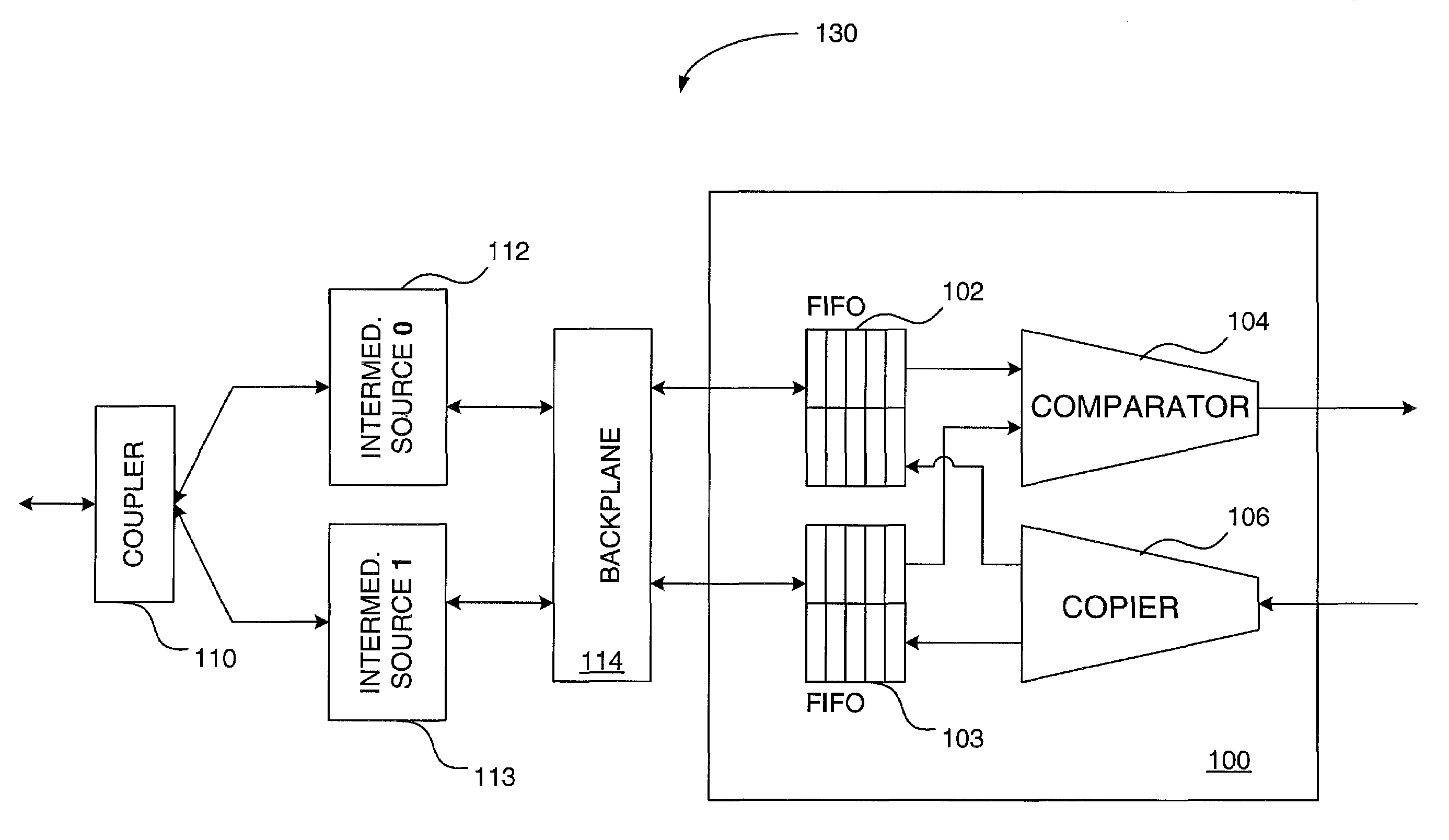
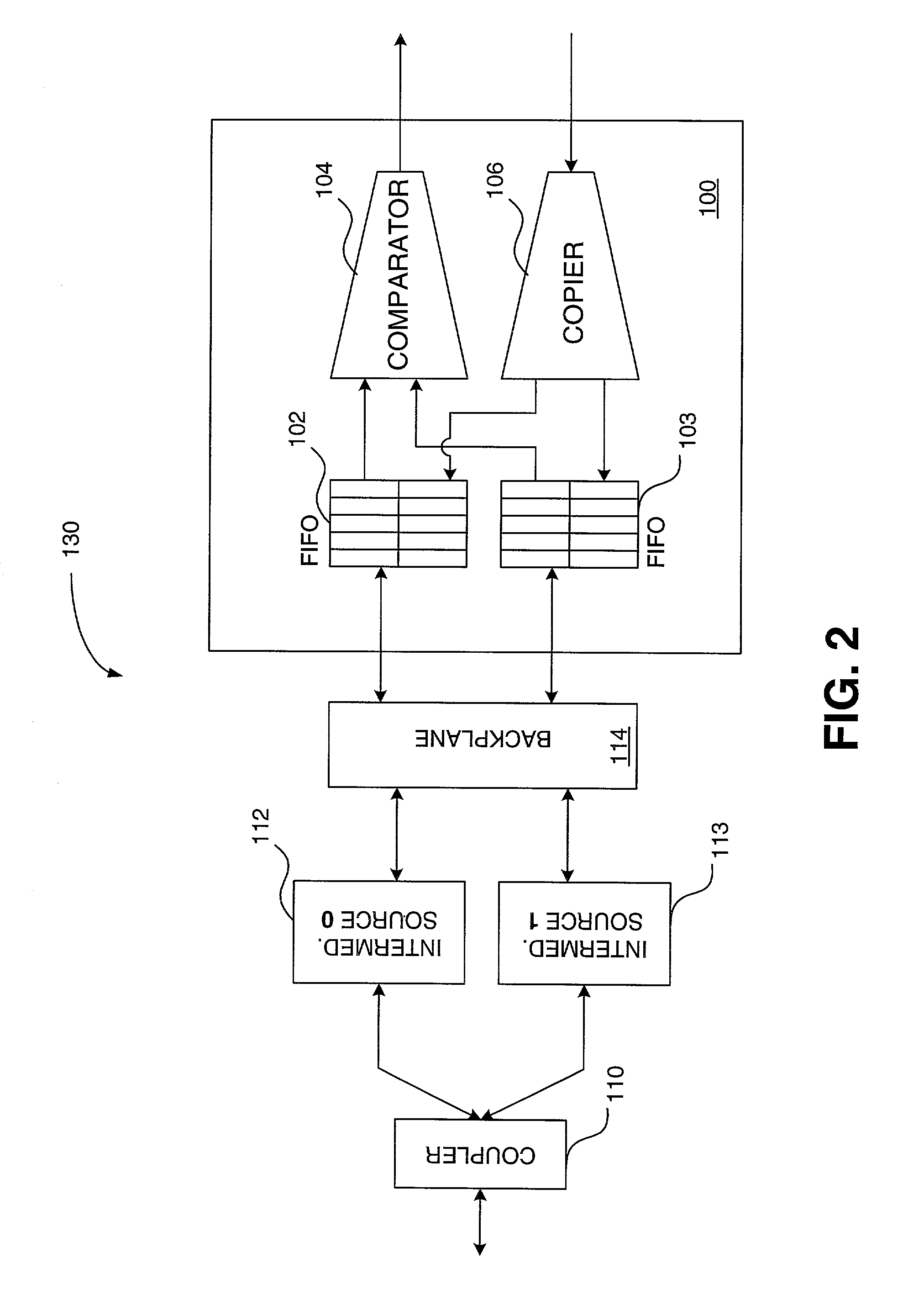
[0038]FIG. 2 is a block diagram of an exemplary packet lockstep mechanism 100 in conjunction with associated input components, in accordance with an embodiment of the present invention. For illustrative purposes, the present invention will be described herein as it operates in an exemplary storage area network (SAN) environment. The exemplary SAN may utilize currently known network storage / transport technologies and protocols such as Fibre Channel (FC) (specified in a family of American National Standar...


PUM


Abstract

A device for ensuring reliable data packet throughput in a redundant system includes a splitter that creates copies of a data packet and sends each copy to a separate intermediate source for processing, parallel buffers for receiving the processed packets from the intermediate sources, and a comparator for determining whether the data packets are equivalent.

Description

BACKGROUND[0001]1. Field of the Invention[0002]The present invention relates generally to data transmission, and more particularly to a packet lockstep mechanism for ensuring reliable data packet throughput in a redundant system.[0003]2. Description of the Prior Art[0004]With early networked storage systems, files are made available to the network by attaching storage devices to a server, which is sometimes referred to as Direct Attached Storage (DAS). In such a configuration, the server controls and “owns” all of the data on its attached storage devices. A shortcoming of a DAS system is that when the server is off-line or not functioning properly, its storage capability and its associated files are unavailable.[0005]At least the aforementioned shortcoming in DAS systems led to Network Attached Storage (NAS) technology and associated systems, in which the storage devices and their associated NAS server are configured on the “front-end” network between an end user and the DAS servers...

Claims


Application Information

Patent Timeline
Patent Type & Authority Patents(United States)
IPC IPC(8): G06F3/00
CPCG06F11/0727G06F11/1625H04L67/1097H04L1/22H04L49/90G06F11/079G06F11/1675
Inventor CHAMDANI, JOSEPH I.CORWIN, MICHAEL
Owner AVAGO TECH INT SALES PTE LTD
Why Eureka
Try Eureka