Force-balanced roller-cone bits, systems, drilling methods, and design methods

a roller-cone and force-balance technology, applied in the field of downhole drilling, can solve the problems of hard teeth inducing compressive failure in formation, bit will not operate as designed, damping is not enough to prevent oscillation, etc., to achieve the effect of reducing gyration, improving drilling efficiency, and underestimating the performance of roller-cones

Inactive Publication Date: 2006-01-17
HALLIBURTON ENERGY SERVICES INC
View PDF110 Cites 52 Cited by
  • Summary
  • Abstract
  • Description
  • Claims
  • Application Information

AI Technical Summary

Benefits of technology

[0035]The applicant has discovered, and has experimentally verified, that equalization of downforce per cone is a very important (and greatly underestimated) factor in roller cone performance. Equalized downforce is believed to be a significant factor in reducing gyration, and has been demonstrated to provide substantial improvement in drilling efficiency. The present application describes bit design procedures which provide optimization of downforce balancing as well as other parameters.
[0036]A roller-cone bit will always be a strong source of vibration, due to the sequential impacts of the bit teeth and the inhomogeneities of the formation. However, many results of this vibration are undesirab

Problems solved by technology

As the drill string rotates, and the cones roll along the bottom of the hole, the individual hard teeth will induce compressive failure in the formation.
The oscillations are damped somewhat by the drilling mud, or by friction where the drill pipe rubs against the walls, or by the energy absorbed in fracturing the formation: but often these sources of damping are not enough to prevent oscillation.
Since these oscillations occur down in the wellbore, they can be hard to detect, but they are generally undesirable.
Drill string oscillations change the instantaneous force on the bit, and that means that the bit will not operate as designed.
For example, the bit may drill oversize, or off-center, or may wear out much sooner than expected.
Oscillations are hard to predict, since different mechanical forces can combine to produce “coupled modes”; the problems of gyration and whirl are an example of this.
The rock will fail when the applied load exceeds the strength of the rock.
Thus as the drill bit is rotated, the cones typically do not roll true, and a certain amount of gouging and scraping takes place.
Many other design parameters are limited in that an increase in one parameter may necessarily result in a decrease of another.
For example, increases in tooth length may cause interference with the adjacent cones.
As can be seen by the forgoing discussion, this is a complex problem.
For many years it has been known that rock failure is compl

Method used


Image

  • Force-balanced roller-cone bits, systems, drilling methods, and design methods
  • Force-balanced roller-cone bits, systems, drilling methods, and design methods
  • Force-balanced roller-cone bits, systems, drilling methods, and design methods

Examples


Embodiment Construction

[0069]The numerous innovative teachings of the present application will be described with particular reference to the presently preferred embodiment (by way of example, and not of limitation).

Rock Bit Computer Model

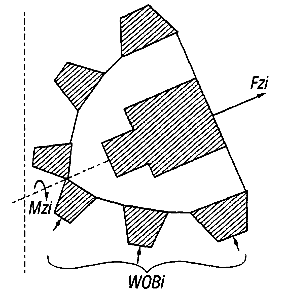
[0070]The present invention uses a single element force-cutting relationship in order to develop the total force-cutting relationship of a cone and of an entire roller cone bit. Looking at FIG. 1, each tooth, shown on the right side, can be thought of as composed of a collection of elements, such as are shown on the left side. Each element used in the present invention has a square cross section with area Se (its cross-section on the x-y plane) and length Le (along the z axis). The force-cutting relationship for this single element may be described by:

Fze=ke*σ*Se  (1)

Fxe=μx*Fze  (2)

Fye=μy*Fze  (3)

where Fze is the normal force and Fxe, Fye are side forces, respectively, σ is the compressive strength, Se the cutting depth and ke, μx and μy are coefficient associated with fo...


PUM


Abstract

Roller cone drilling wherein the bit optimization process equalizes the downforce (axial force) for the cones (as nearly as possible, subject to other design constraints).

Description

CROSS-REFERENCE TO OTHER APPLICATIONS[0001]This application is a continuation of U.S. patent application Ser. No. 10 / 383,805 filed by Shilin Chen on Mar. 8, 2003, which is a continuation of U.S. patent application Ser. No. 09 / 833,016 filed by Shilin Chen on Apr. 10, 2001, which is a continuation of U.S. patent application Ser. No. 09 / 387,737 filed by Shilin Chen on Aug. 31, 1999, now U.S. Pat. No. 6,213,225, which claims the benefit of U.S. Provisional Application Ser. No. 60 / 098,466 filed on Aug. 31, 1998, which is hereby incorporated by reference.BACKGROUND AND SUMMARY OF THE INVENTION[0002]The present invention relates to down-hole drilling, and especially to the optimization of drill bit parameters.[0003]BACKGROUND: ROTARY DRILLING[0004]Oil wells and gas wells are drilled by a process of rotary drilling, using a drill rig such as is shown in FIG. 10. In conventional vertical drilling, a drill bit 10 is mounted on the end of a drill string 12 (drill pipe plus drill collars), whic...

Claims


Application Information

Patent Timeline
IPC IPC(8): E21B10/16E21B10/08E21B41/00
CPCE21B10/08E21B49/00E21B10/16
Inventor CHEN, SHILIN
Owner HALLIBURTON ENERGY SERVICES INC
Why Eureka
Try Eureka