

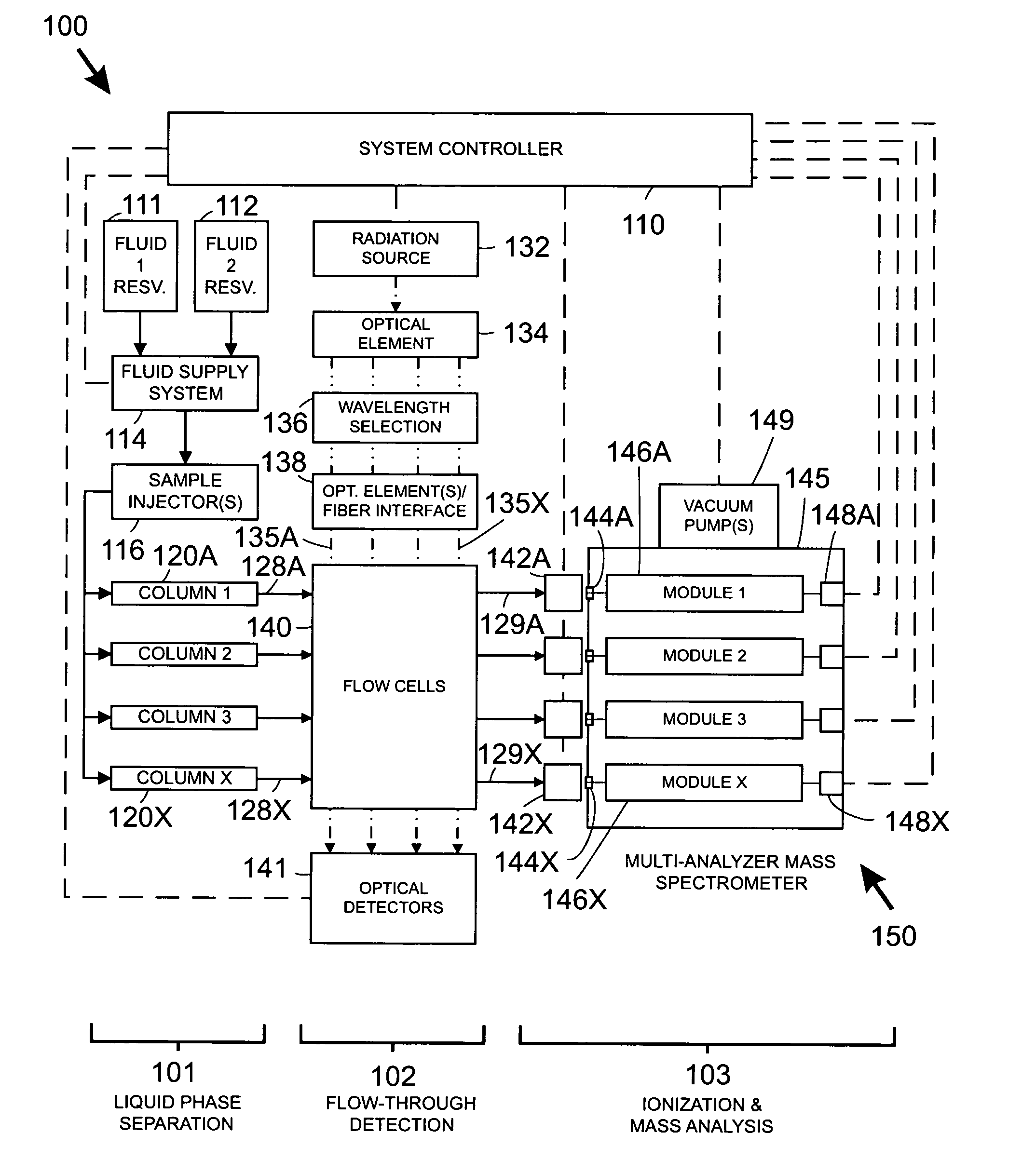
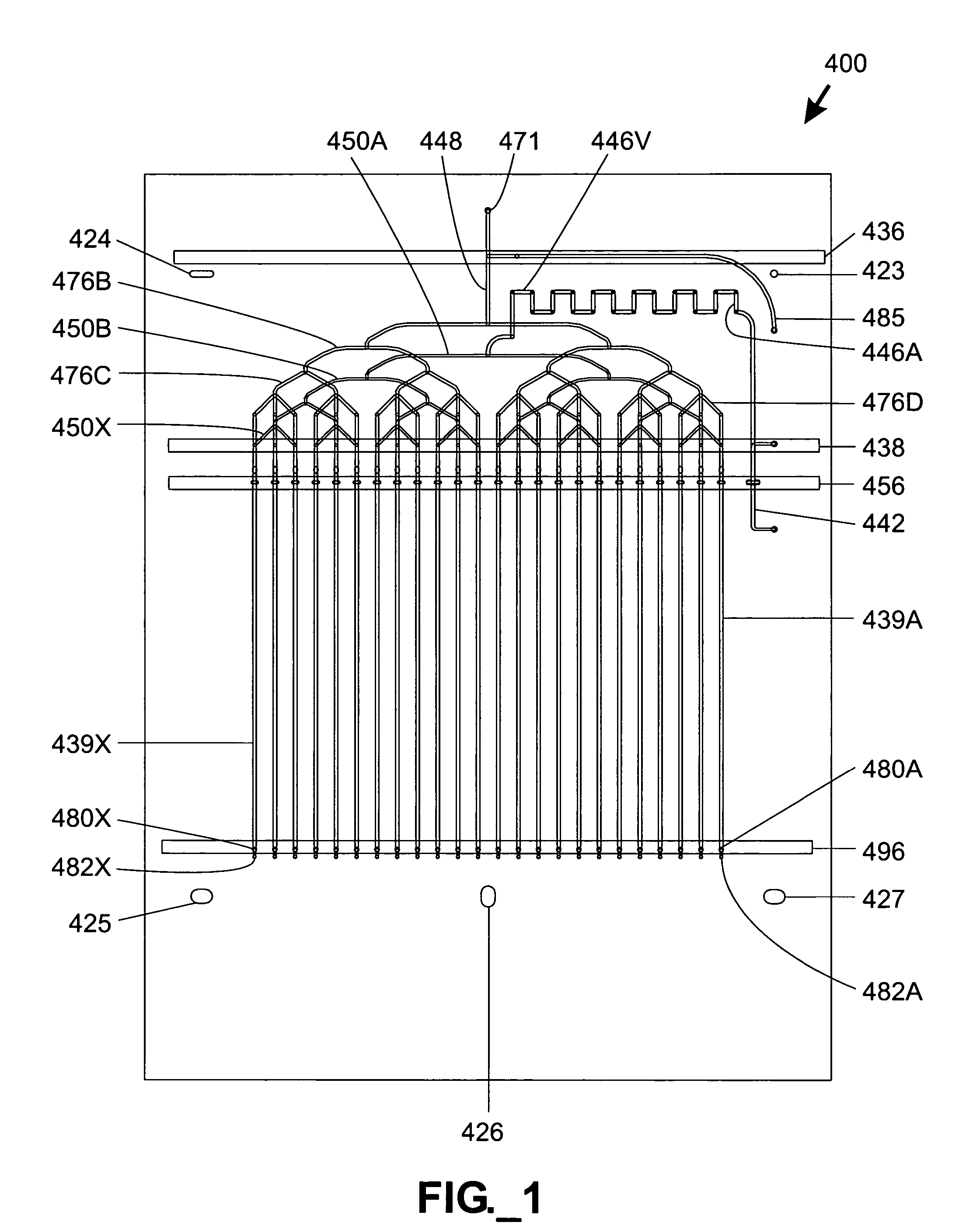
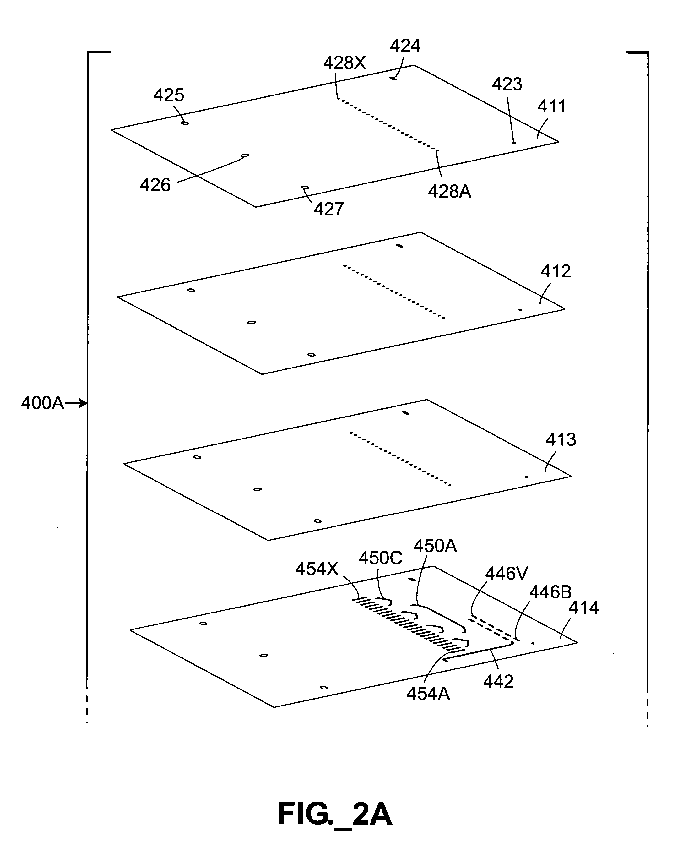
High throughput systems and methods for parallel sample analysis
a sample analysis and high throughput technology, applied in the field of high throughput systems and methods for parallel sample analysis, can solve the problems of inability to identify or characterize individual components, inability to integrate fluid phase separation/ms systems, and successive instability of increasing mass-to-charge ratios
- Summary
- Abstract
- Description
- Claims
- Application Information
AI Technical Summary
Problems solved by technology
Method used
Image

Examples
Embodiment Construction
Definitions
[0042]The terms “column” or “separation column” as used herein are used interchangeably and refer to a region of a fluidic device that contains stationary phase material and is adapted to perform a chromatographic separation process.
[0043]The term “fluid phase separation process region” refers to any region adapted to perform a fluid (i.e., liquid or gas) phase chemical or biochemical analytical process such as chromatographic, electrophoretic, electrochromatographic, immunoaffinity, gel filtration, and / or density gradient separation.
[0044]The term “interpenetrably bound” as used herein refers to the condition of two adjacent polymer surfaces being bound along a substantially indistinct interface resulting from diffusion of polymer chains from each surface into the other.
[0045]The term “mass analyzer” as used herein refers to an analytical component that serves to separate ions electromagnetically based on their charge / mass ratio.
[0046]The term “microfluidic” as used here...
PUM
 Abstract
Description
Claims
Application Information