Sense amplifying latch with low swing feedback

a technology of low swing feedback and sense, applied in the field of data transfer, can solve the problems of inability to transmit and receive signals across capacitive pads, bottlenecks that continue to grow, and advances in semiconductor technology that have not been matched by corresponding advances in inter-chip communication technology

Inactive Publication Date: 2006-01-17
ORACLE INT CORP
View PDF14 Cites 22 Cited by
  • Summary
  • Abstract
  • Description
  • Claims
  • Application Information

AI Technical Summary

Benefits of technology

[0019]In a further variation, the system adjusts the RC time constant for the feedback signal so that the time constant for the feedback signal is significantly larger than the time constant for the transmitted signal from the capacitive transmitter pad, thereby ensuring that the feedback signal does not mask transitions of the transmitted signal.

Problems solved by technology

Unfortunately, these advances in semiconductor technology have not been matched by corresponding advances in inter-chip communication technology.
This problem creates a bottleneck that continues to grow as semiconductor integration densities continue to increase.
However, it is not a simple matter to transmit and receive signals across capacitive pads.
One problem is that signals become attenuated by the relatively large capacitance caused by layers of metal and silicon dioxide underneath the capacitive pads.
Unfortunately, increasing the sensitivity of the circuitry to small signals also increases the sensitivity of the circuit to noise.
Reducing the sensitivity of the circuit to noise also reduces the sensitivity of the circuitry to small signals.

Method used


Image

  • Sense amplifying latch with low swing feedback
  • Sense amplifying latch with low swing feedback
  • Sense amplifying latch with low swing feedback

Examples


Embodiment Construction

[0028]The following description is presented to enable any person skilled in the art to make and use the invention, and is provided in the context of a particular application and its requirements. Various modifications to the disclosed embodiments will be readily apparent to those skilled in the art, and the general principles defined herein may be applied to other embodiments and applications without departing from the spirit and scope of the present invention. Thus, the present invention is not intended to be limited to the embodiments shown, but is to be accorded the widest scope consistent with the principles and features disclosed herein.

Inter-Chip Communication through Capacitive Coupling

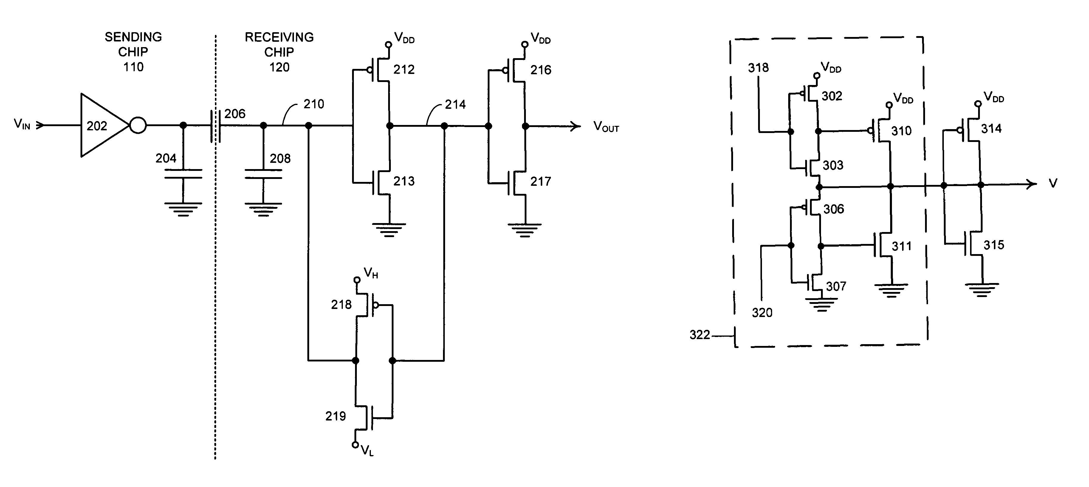
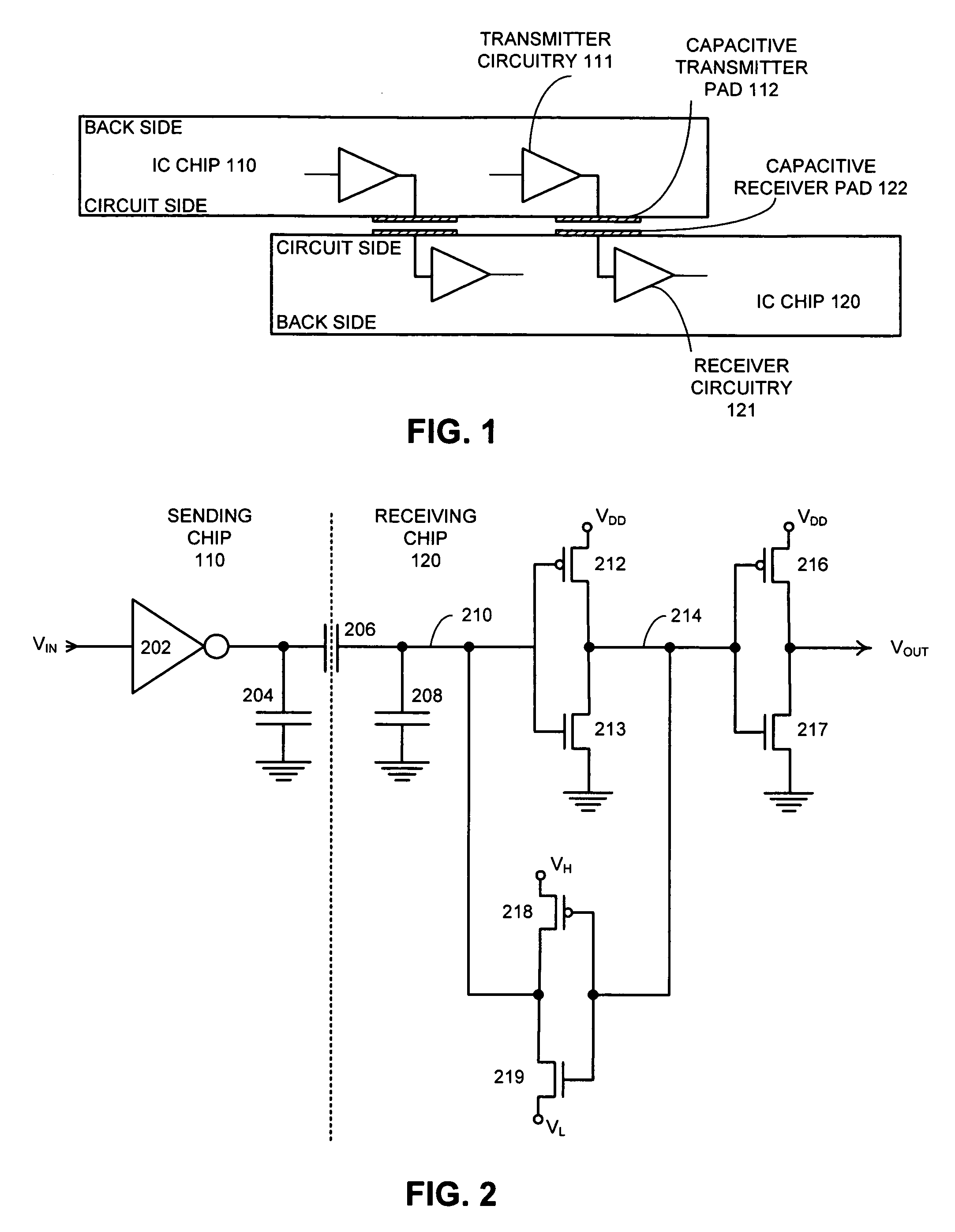
[0029]FIG. 1 illustrates inter-chip communication through capacitive pads in accordance with an embodiment of the present invention. The transmitting integrated circuit (IC) chip 110 contains transmitter circuitry 111, which feeds a signal into a capacitive transmitter pad 112. The signal is c...


PUM


Abstract

A system is presented for latching and amplifying a capacitively coupled inter-chip communication signal that operates by receiving an input signal on a capacitive receiver pad and feeding the input signal through an inverter to produce an output signal. The output signal is fed back through a weakened inverter to produce a feedback signal that is fed into an input of the inverter to form a latch for the input signal. The weakened inverter is biased to produce a feedback signal that swings between a high bias voltage, VH, and a low bias voltage, VL. VH is set slightly higher than the switching threshold of the inverter, and VL is set slightly lower than the switching threshold. This feedback signal causes the input signal to reside within a narrow voltage range near the switching threshold of the inverter, thereby making the inverter sensitive to small transitions in the input signal.

Description

RELATED APPLICATION[0001]This application hereby claims priority under 35 U.S.C. 119 to U.S. Provisional Patent Application No. 60 / 460,105, filed on 2 Apr. 2003, entitled “Sense Amplifying Latch with Low Swing Feedback,” by inventors Ivan E. Sutherland, Robert J Bosnyak, and Robert J. Drost.[0002]The subject matter of this application is related to the subject matter in a co-pending non-provisional application by Robert J. Proebsting and Robert J. Bosnyak entitled, “Method and Apparatus for Amplifying Capacitively Coupled Inter-Chip Communication Signals,” having Ser. No. 10 / 772,106, and filing date 2 Feb. 2004.GOVERNMENT LICENSE RIGHTS[0003]This invention was made with United States Government support under Contract No. NBCH020055 awarded by the Defense Advanced Research Projects Administration. The United States Government has certain rights in the invention.BACKGROUND[0004]1. Field of the Invention[0005]The present invention relates to the process of transferring data between int...

Claims


Application Information

Patent Timeline
Patent Type & Authority Patents(United States)
IPC IPC(8): H03K3/356H03L5/00H01L23/48H01L25/065H03K3/037H03K5/003H03K17/689
CPCH01L23/48H01L25/0657H03K3/037H03K5/003H01L2225/06527H01L2924/0002H01L2924/00013H03K17/689H01L2224/13099H01L2224/13599H01L2224/05599H01L2224/05099H01L2224/29099H01L2224/29599H01L2924/00H03K3/0377H03K19/018571
Inventor SUTHERLAND, IVAN E.BOSNYAK, ROBERT J.DROST, ROBERT J.
Owner ORACLE INT CORP
Why Eureka
Try Eureka