Molecular detection using an optical waveguide fixed to a cantilever

a cantilever and optical waveguide technology, applied in the field of detecting molecules, can solve the problems of difficult or impossible to perform many known molecular detection techniques, limited molecular detection techniques, and difficulty in isolating molecules, so as to facilitate the immobilization of receptors, enhance bonding, and improve light transmission through the waveguide

Active Publication Date: 2006-01-17
LUCENT TECH INC
View PDF8 Cites 37 Cited by
  • Summary
  • Abstract
  • Description
  • Claims
  • Application Information

AI Technical Summary

Benefits of technology

[0006]The waveguide can be integral with the cantilever or attached thereto. Alternatively, the waveguide can rest upon or otherwise contact the second body in a configuration such that deflection of the cantilever reduces light coupling of the gapped ends of the waveguide.
[0007]The first body, the second body, or both can have a cladding material applied thereto or integral therewith, to improve light transmission through the waveguide.
[0008]The first and second bodies can be fabricated from substantially any material. The two bodies can be integral parts of a single substrate, or they can be separate pieces. A first metallic layer can be interposed between the receptor and the face of the cantilever in order to facilitate immobilization of the receptor on the cantilever. A second metallic layer can be interposed between the first metallic layer and the face of the cantilever, to enhance bonding between the cantilever face and the first metallic layer.
[0009]The shape of the cantilever is within the implementer's discretion. Examples of suitable shapes include substantially rectangular cantilevers and those that are wedge- or V-shaped. Temperature-induced fluctuations in cantilever deflection can be avoided by maintaining the cantilever (or the entire detector) at substantially the same temperature as the fluid.

Problems solved by technology

Many molecular detection techniques are limited by low a concentration of the molecule, a relatively high concentration of similar molecules, difficulty in isolating the molecule, and similar drawbacks.
As a result, many known molecular detection techniques are difficult or impossible to perform, and results obtained using such methods can be inaccurate.
A drawback shared by most prior detection methods is that they require that a member of the binding pair, or the bound pair, be detectably labeled.
In addition to increasing the labor requirement and complexity of the test, such labeling can interfere with the assay results.
Binding of the other pair member with the immobilized pair member induces a stress on the face of the cantilever having the immobilized pair member thereon, resulting in bending of the cantilever.
A difficulty experienced using nanoscale cantilever-based binding detectors based on reflected light is that the devices are highly sensitive to minute vibrations.
Any misalignment of the optical beam severely degrades the optical signal.

Method used


Image

  • Molecular detection using an optical waveguide fixed to a cantilever
  • Molecular detection using an optical waveguide fixed to a cantilever

Examples


examples

[0096]The invention is now described with reference to the following Examples. These Examples are provided for the purpose of illustration only, and the invention is not limited to these Examples, but rather encompasses all variations which are evident as a result of the teaching provided herein.

[0097]Fabrication of a Multiple Cantilever Detector

[0098]This example describes how a detector described herein can be fabricated.

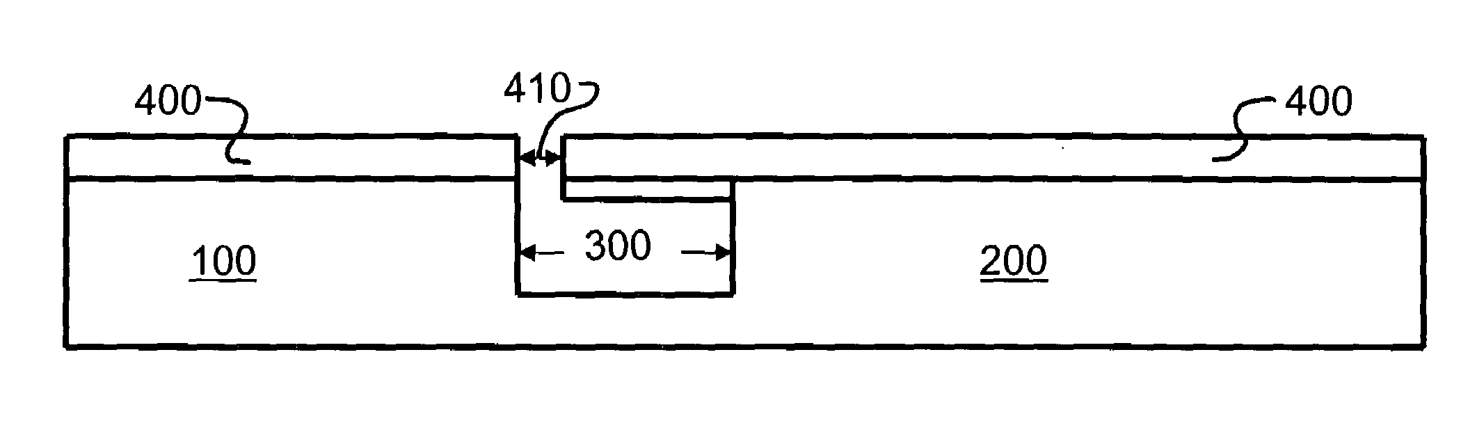
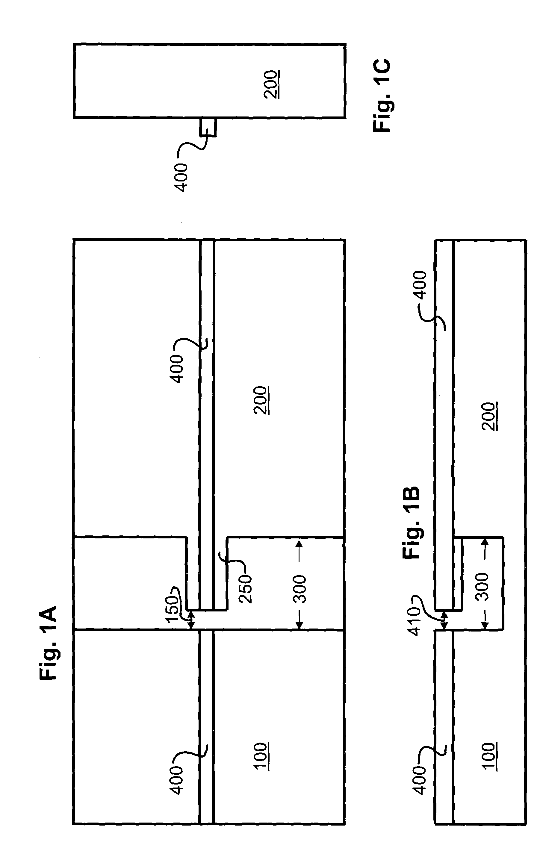
[0099]A double-sided polished silicon wafer having a substantially uniform thickness of about 250 micrometers is used as a substrate. The silicon substrate is immersed in a boiling 6:1:1 mixture of distilled, de-ionized water (DDW):ammonium hydroxide:hydrogen peroxide. After rinsing, the substrate is immersed in a boiling bath of a 6:1:1 mixture of DDW:hydrochloric acid:hydrogen peroxide in order to clean the surface thereof. After rinsing with DDW, the wafer is immersed in concentrated hydrofluoric acid for 5 minutes. The wafer is rinsed again with a copious amou...


PUM

PropertyMeasurementUnit
angleaaaaaaaaaa
angleaaaaaaaaaa
angleaaaaaaaaaa

Abstract

The invention relates to devices and methods for detecting a ligand in a liquid, based on deflection of one or more microscopic cantilevers. Each cantilever has an optical waveguide fixed thereto or integral therewith. Deflection of the cantilever is detected by assessing coupling of light between the optical waveguide on the cantilever and an optical waveguide fixed distally thereto.

Description

TECHNICAL FIELD[0001]The invention relates generally to the field of detecting molecules using microscopic cantilever-based devices.BACKGROUND OF THE INVENTION[0002]Detection of a molecule, e.g., a nucleic acid, a polypeptide, a carbohydrate, or a combination thereof, or binding between a molecule and a binding partner of the molecule is a common assay technique. Many molecular detection techniques are limited by low a concentration of the molecule, a relatively high concentration of similar molecules, difficulty in isolating the molecule, and similar drawbacks. As a result, many known molecular detection techniques are difficult or impossible to perform, and results obtained using such methods can be inaccurate. A drawback shared by most prior detection methods is that they require that a member of the binding pair, or the bound pair, be detectably labeled. In addition to increasing the labor requirement and complexity of the test, such labeling can interfere with the assay results...

Claims


Application Information

Patent Timeline
Patent Type & Authority Patents(United States)
IPC IPC(8): G02B6/00G01N33/543G02B6/35
CPCG01N33/54373G02B6/3566G02B6/3502
Inventor TRAN, ALEX T.CARR, DUSTIN W.
Owner LUCENT TECH INC
Why Eureka
Try Eureka