Deformable mirror actuation system

a mirror and actuator technology, applied in the direction of optical elements, photomechanical devices, instruments, etc., can solve the problems of not widely used use of lithographic exposure by exposing a mask in close proximity to the wafer, unable to meet the requirements of lithographic exposure, and the manufacturing process of reticles for electron beam projection is much less developed, so as to achieve the effect of optimizing optical performan

Inactive Publication Date: 2006-01-24
NIKON CORP
View PDF10 Cites 23 Cited by
  • Summary
  • Abstract
  • Description
  • Claims
  • Application Information

AI Technical Summary

Benefits of technology

[0010]The present invention provides an optical system operable at EUV wavelengths employing stable mechanical control of one or more adaptive optical elements for optimization of optical performance and minimization of aberrations. The invention also provides an apparatus and method for optical element deformation by mechanical actuation that controls the local deformation of areas of an optical element to provide desired or aberration-compensating performance of the optical system.

Problems solved by technology

Nevertheless, resolution of extremely small features requires correspondingly short wavelengths of radiation.
Accordingly, use of X-rays for lithographic exposure by exposing a mask in close proximity to the wafer is known but not widely used due to the requirement for fabrication of an exposure mask at the same minimum feature size as the final desired pattern.
Between these two techniques, the manufacturing process for reticles for electron beam projection is much less developed than for optical reticles and, perhaps more importantly, require many more exposures to form a complete integrated circuit pattern since the exposure field at the chip is comparatively more limited in electron beam projection systems.
While techniques of measurement of wave-front aberrations are well-known and sufficient to accurately characterize the performance of optical systems and elements thereof, practical arrangements for conducting such measurements are difficult and complex.
Measurements performed between exposures may not be regarded as measurements of optical performance during the exposure and do not directly characterize the lithographic image, itself, but are often the only practical solution at the current state of the art even though sources of error may be introduced.
However, mechanical actuators which deflect portions of the optical element such as are disclosed therein may present numerous problems of stability, hysteresis and the like and may be unsuitable for optical element deformations which may be only a relatively small fraction of a very short wavelength.
In addition, if measurements of the optical system properties can only be performed at intervals between exposures, the stability of the optical element adjustment becomes critical.

Method used


Image

  • Deformable mirror actuation system
  • Deformable mirror actuation system
  • Deformable mirror actuation system

Examples


Embodiment Construction

[0021]Referring now to the drawings, and more particularly to FIG. 7A, there is shown an exemplary catroptic optical system with which the invention may be employed as well as in any reflective element of any optical system. All optical elements of this system are reflective and thus the optical system is suitable for projection of EUV wavelengths. The illustrated optical system is suitable for image projection of a pattern established by the reticle onto a target such as a resist-coated wafer. It should be further noted that this optical system is relatively complex; including six mirrors and having a folded optical path among the elements and principally off-axis which, itself, may give rise to significant aberrations.

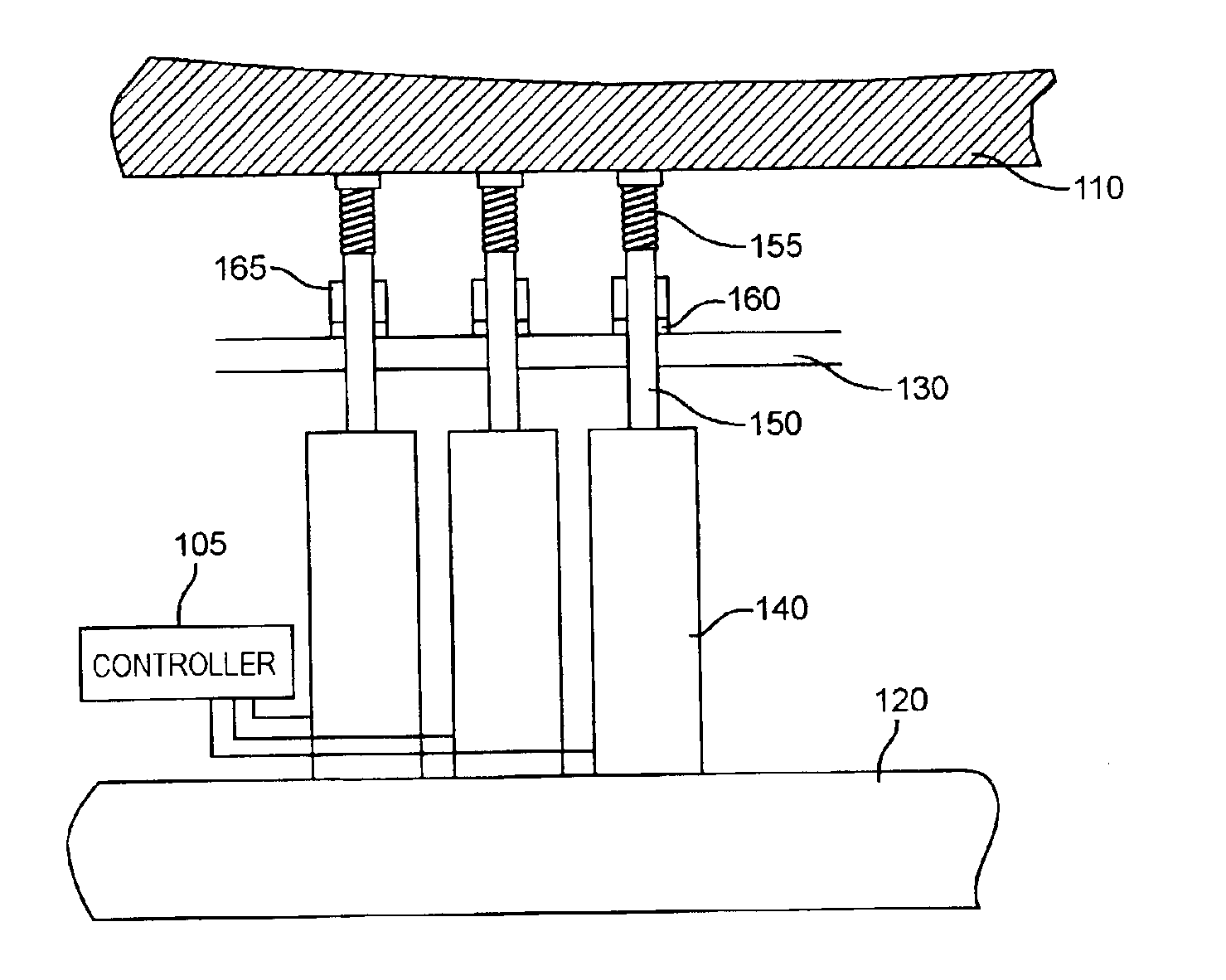
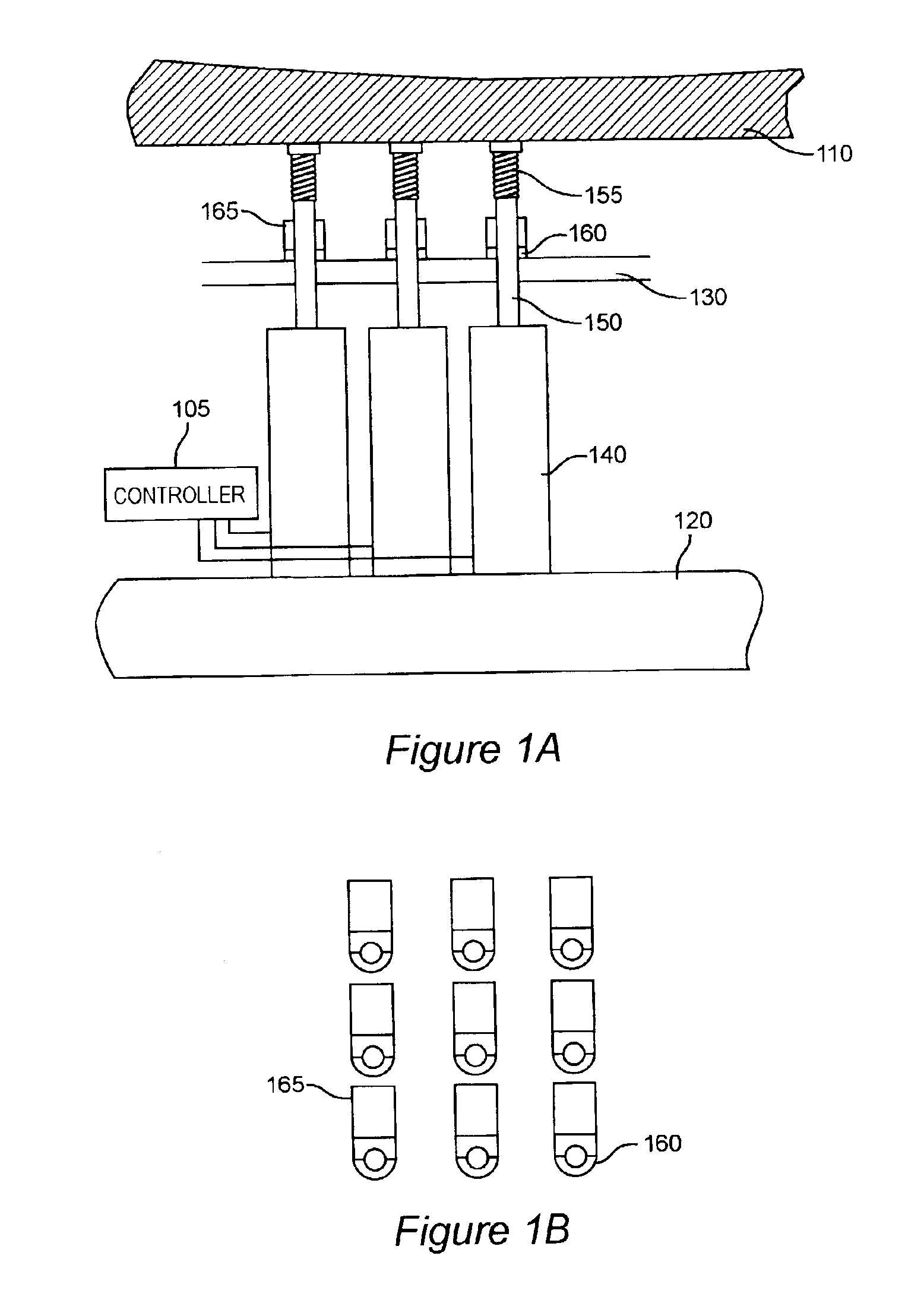
[0022]Deformable mirrors are used in adaptive optics to alter the properties of a system in real time. The deformable mirror forms part of the optical system. The wave front of light transmitted through the optical system is measured and the shape of the mirror is ad...


PUM

PropertyMeasurementUnit
wavelengthsaaaaaaaaaa

Abstract

Mechanical control and actuation of an adaptive optical element provides highly stable and repeatable correction of the shape of an optical element to an accuracy of a small fraction of a very short wavelength of light, responsive to a metrology source and sensor arrangement. Actuators in the form of individual set-screws or other actuators capable of axially positioning a shaft are driven by a robotic screw driver with four degrees of freedom or one or more linear actuators to exert force on the mirror. Positive or negative force may be used for outward and / or inward deflection of the mirror. When a desired force is developed on the mirror through a mechanical linkage, the linkage may be clamped by a passive clamp which may be released by an actuator such that the adjustment is maintained while the linear actuator and the clamp actuator are turned off; yielding a highly stable adjustment while effectively removing sources of actuator drift, noise, vibration and heating which may adversely affect stability.

Description

CROSS-REFERENCE TO RELATED APPLICATIONS[0001]This application claims priority of U.S. Provisional Patent Application Ser. No. 60 / 390,158, filed Jun. 21, 2002, entitled “Deformable Mirror Actuation System” which is hereby fully incorporated by reference.BACKGROUND OF THE INVENTION[0002]1. Field of the Invention[0003]The present invention generally relates to high precision imaging using a reflective optical element and, more particularly, to high precision lithography exposure systems and methods using one or more adaptive, reflective optical elements to minimize aberrations and measurement and control therefor.[0004]2. Description of the Prior Art[0005]Many manufacturing and scientific processes require the use of optical systems having extremely high accuracy and freedom from aberrations as well as the ability to make observations and / or exposures in wavelength regimes well outside the visible spectrum. For example, at least one lithographic exposure process is invariably required ...

Claims


Application Information

Patent Timeline
Patent Type & Authority Patents(United States)
IPC IPC(8): G02B26/08G02B27/00G02B26/00G02B5/10G02B7/182G03F7/20H01L21/027
CPCG02B26/0825G03F7/70275G03F7/70266G03F7/70233
Inventor PHILLIPS, ALTONSOGARD, MICHAEL
Owner NIKON CORP
Why Eureka
Try Eureka