Antisoiling coatings for antireflective substrates

a technology of anti-reflective substrates and anti-soiling coatings, which is applied in the direction of anti-reflective coatings, instruments, optical elements, etc., can solve the problems of easy contamination and difficult cleaning, easy to be damaged, and easily compromised anti-reflective properties,

Inactive Publication Date: 2006-01-31
3M INNOVATIVE PROPERTIES CO
View PDF16 Cites 54 Cited by
  • Summary
  • Abstract
  • Description
  • Claims
  • Application Information

AI Technical Summary

Benefits of technology

[0053]Advantages of the invention are illustrated by the following examples. The particular materials and amounts thereof recited in these examples, as well as other conditions and details, are to be interpreted to apply broadly in the art and should not be construed to unduly limit the invention.

Problems solved by technology

The transparency of glass or plastic, in the form of doors, windows, lenses, filters, display devices (e.g., display panels) of electronic equipment, and the like, can be impaired by glare or reflection of light.
If left untreated, the high surface energy and porous structure of the antireflective stack render it easily contaminated and difficult to clean.
Furthermore, the antireflective properties are extremely sensitive to and easily compromised by trace levels of organic contamination such as skin oils.
The durability of these films, however, to dry rub abrasion is relatively poor, and the industry continues to search for a treatment with better initial oil and stain repellency.

Method used


Image

  • Antisoiling coatings for antireflective substrates

Examples


example 1

Vapor Deposition of HFPO Silane

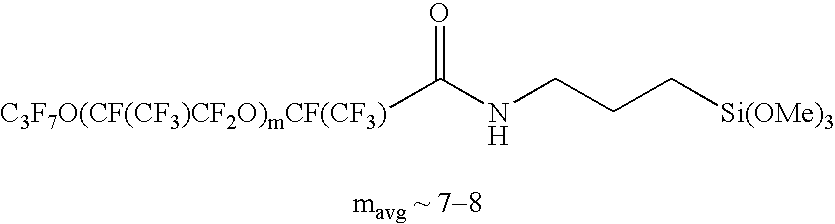
[0061]Into Vapor Deposition Chamber 1 was placed a 5 dram vial containing about 3 drops of HFPO Silane, and a microscope slide (25×75 mm; available from VWR Scientific, West Chester. PA). Using a silicone oil vacuum pump, a vacuum of 0.002 mm Hg (0.27 Pascal) was achieved and the chamber was then heated to 90° C. (outer glass temperature) using a heating mantle. The sample was subjected to this heat and pressure for one hour, then the chamber was cooled, the vacuum was broken and the chamber opened. The ensuing coated sample was tested using the water Static Contact Angle Measurement test listed above. Results are listed in Table 1

example 2

Vapor Deposition of PFPE Disilane

[0062]Into Vapor Deposition Chamber 1 was placed a 5 dram vial containing about 3 drops of PFPE disilane and a microscope slide (25×75 mm). Using a silicone oil vacuum pump, a vacuum of 0.003 mm Hg (0.4 Pascal) was achieved and the chamber was then heated to 150° C. (outer glass temperature) using a heating mantle. The sample was subjected to this heat and pressure for 30 minutes, then the chamber was cooled, the vacuum was broken and the chamber opened. The ensuing coated sample was tested using the water Static Contact Angle Measurement test listed above. Results are listed in Table 1

examples 3 – 8

Examples 3–8

[0065]Examples 3–8 were prepared by first using a heating mantle to heat the Vapor Deposition Chamber 1 to the temperature listed in Table 2. The temperature was measured on the inside of the chamber (1 cm from the sample location). Then a 5 dram vial containing about 3 drops of the fluorochemical (FC) as listed in Table 2 and a microscope slide (25×75 mm) were placed into the chamber. Using a silicone oil vacuum pump, the heated chamber was subjected to a vacuum of 0.002 mm Hg (0.27 Pascal). The sample was subjected to this heat and pressure for 3 minutes, then the chamber was cooled, the vacuum was broken and the chamber opened. The ensuing coated sample was tested using the Abrasion / Scrub Test and water and hexadecane Static Contact Angle Measurement tests listed above. The results are listed in Table 2


PUM

PropertyMeasurementUnit
pressuresaaaaaaaaaa
temperaturesaaaaaaaaaa
thicknessaaaaaaaaaa

Abstract

This invention relates to antisoiling compositions for antireflective substrates. More particularly, this invention relates to methods for depositing antisoiling compositions onto antireflective substrates. In particular, this invention relates to a method of depositing an antisoiling composition on an antireflective substrate comprising vaporizing an antisoiling composition and depositing the antisoiling composition onto an antireflective substrate. In another aspect, this invention relates to method of preparing an antireflective film stack comprising depositing an antireflective layer onto the surface of a transparent substrate and vapor depositing an antisoiling layer onto the surface of the antireflective layer. In yet another aspect, this invention relates to a method of depositing an antisoiling composition on an antireflective coated ophthalmic lens comprising vaporizing an antisoiling composition and depositing the antisoiling composition onto an antireflective coated ophthalmic lens.

Description

FIELD OF INVENTION[0001]This invention relates to antisoiling coatings for antireflective substrates. More particularly, this invention relates to methods for depositing antisoiling coatings onto antireflective substrates.BACKGROUND OF THE INVENTION[0002]The transparency of glass or plastic, in the form of doors, windows, lenses, filters, display devices (e.g., display panels) of electronic equipment, and the like, can be impaired by glare or reflection of light. To reduce the amount of glare, for example, on plastic or glass, the surface typically includes a single layer of metal oxide (such as silicon dioxide), a metal fluoride, a metal nitride, a metal sulfide, or the like. Such coatings function as antireflective coatings.[0003]Antireflective coated lenses represent a relatively small but rapidly growing segment of the ophthalmic lens market. These antireflective coated lenses are finding favor among consumers due to their enhanced cosmetic aspects and increased transmittance. I...

Claims


Application Information

Patent Timeline
Patent Type & Authority Patents(United States)
IPC IPC(8): C23C14/12G02B1/10G02C7/02C23C14/24B05D7/24C08G65/22C08J7/043C08J7/046C08J7/048C09D5/00C09D171/00C09D183/08C09D183/12
CPCC08G65/226C08J7/06C09D4/00C09D5/006C09D5/1668C09D5/1675G02B1/105C09D183/08C09D183/12C23C14/12C08G77/24C08J2369/00G02B1/111G02B1/18C08J7/048C08J7/043C08J7/046
Inventor PELLERITE, MARK J.DAMS, RUDOLF J.MARTIN, STEVEN J.
Owner 3M INNOVATIVE PROPERTIES CO
Why Eureka
Try Eureka