Method for studying a sample and optical interferometer for doing the same

a sample and optical interferometer technology, applied in the field of physical engineering, can solve the problems of affecting the most known sources of broadband optical radiation, the cost of another optical circulator added to the reference arm, and the low etc., to achieve optimal signal-to-noise ratio, simple and cost-effective, and high efficiency of optical source power use

Inactive Publication Date: 2006-01-31
IMALUX CORP
View PDF6 Cites 9 Cited by
  • Summary
  • Abstract
  • Description
  • Claims
  • Application Information

AI Technical Summary

Benefits of technology

[0016]The present invention is directed to a method and apparatus to expand the family of methods and optical interferometers, designed for studying samples with the use of low coherent optical radiation, which ensure highly efficient use of optical source power together with optimal signal-to-noise ratio for a given optical source power and are simple and cost-effective.
[0029]The developed optical interferometer ensures highly efficient use of an optical source power together with optimal signal-to-noise ratio for a given optical source power and is simple and cost-effective.

Problems solved by technology

The major drawback of Michelson interferometers, as well as of the executed method, is the low efficiency of use of optical source power.
This component could be used in another interferometer configuration to improve the signal-to-noise ratio (SNR), but is wasted in the Michelson interferometer and moreover, negatively impacts most known sources of a broadband optical radiation (e.g., semiconductor superluminescent diodes, doped-fiber amplified spontaneous emission superlums, solid state and fiberoptic femtosecond lasers).
It is more common in the art to use reflecting delay lines based on a moving mirror, diffraction grating line, rotating mirrors, prisms, cams, and helicoid mirrors, but with the expense of another optical circulator added into the reference arm.
In comparison with the Michelson interferometer, a transmissive delay line can only provide 50% of optical path modulation (and therefore 50% scanning depth) for the same delay element because of unidirectional rather than bi-directional operation.
A drawback of the hybrid method, as well as the hybrid interferometer described in the International application No.
In addition, some portion of the reference arm power inevitably returns back to the source, which may negatively impact the source performance.

Method used


Image

  • Method for studying a sample and optical interferometer for doing the same
  • Method for studying a sample and optical interferometer for doing the same

Examples


Embodiment Construction

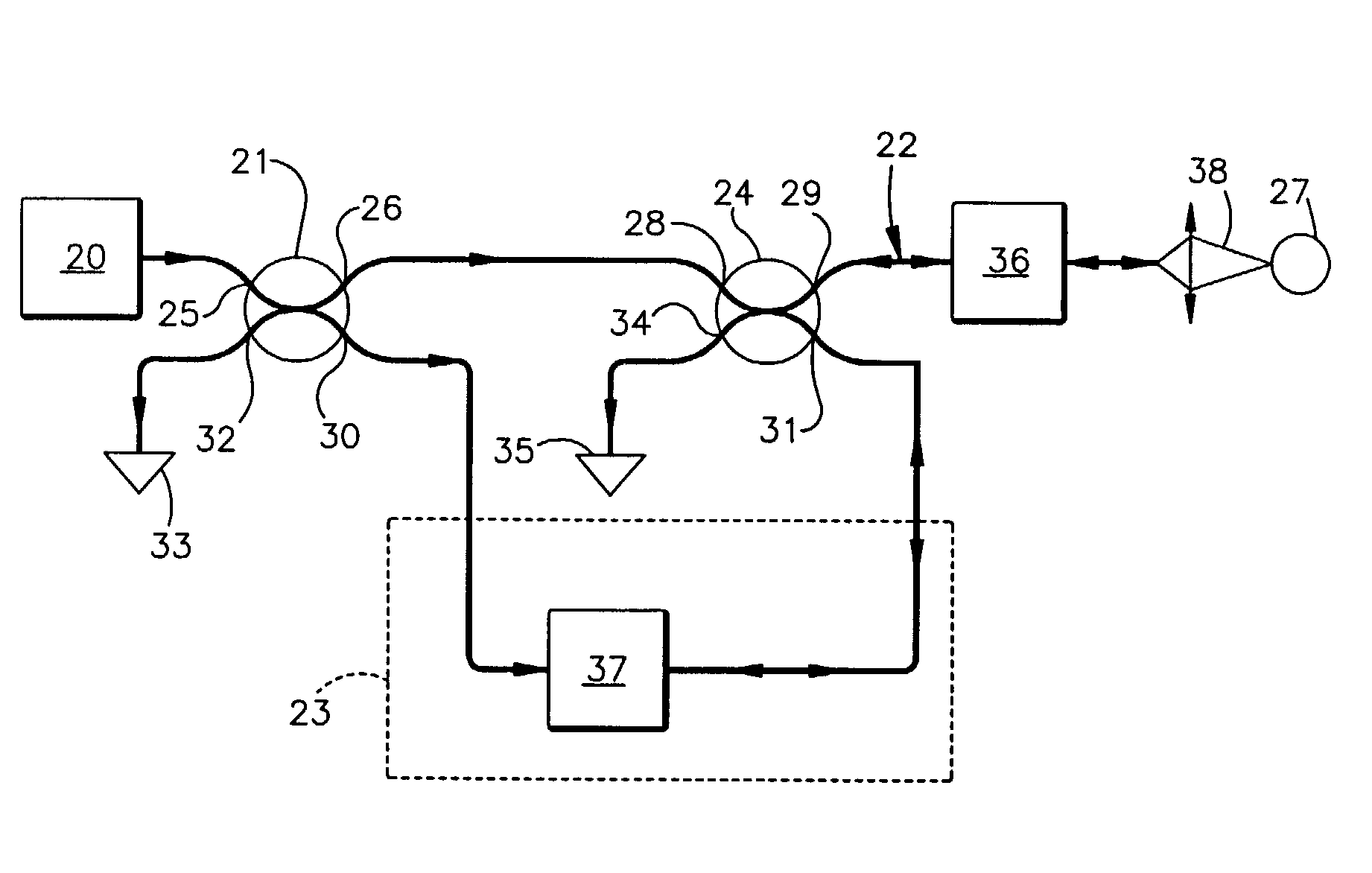
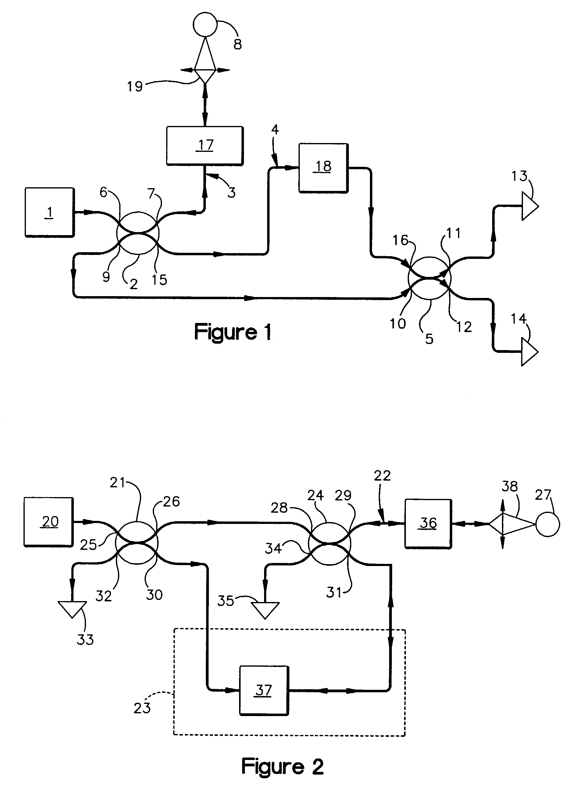
[0035]The optical interferometer is illustrated by means of an example of an optical fiber interferometer being part of a device for optical coherence tomography, although it is evident that they can be implemented with the use of bulk optic elements, and can be used as independent devices. The fiberoptic implementation is preferable for use in medical applications, especially in endoscopy, where flexibility of fiberoptics provides convenient access to different tissues and organs, including internal organs via an endoscope. However, the whole interferometer, or any part of it, can be implemented using traditional bulk optics, e.g., mirrors, prisms etc. Any such modification of the hybrid interferometer with unidirectional reference arm and bi-directional sampling arm is included within the scope of this invention.

[0036]The optical interferometer referred to in FIG. 2, operates as follows.

[0037]A source 20 forms an optical low coherent radiation beam, in a preferred embodiment, in t...


PUM

PropertyMeasurementUnit
penetration depthaaaaaaaaaa
diameteraaaaaaaaaa
optical radiationaaaaaaaaaa

Abstract

The present invention relates to the study of internal structure of objects by optical means. The invention presents a bi-directional sampling optical path for the low coherent optical radiation directed to the sample, i.e. a bi-directional sampling arm, and two unidirectional reference beams directed along a reference path designed as a loop. One of the reference beams propagates clockwise and the other propagates counterclockwise in the reference loop. The beam splitters non-reciprocal or polarization-dependent and by placing polarization-changing elements between the beam splitters and / or into the sampling arm and the reference loop. Thus the developed method and optical interferometer make possible to ensure highly efficient use of optical source power together with optimal signal-to-noise ratio for a given optical source power and are simple and cost effective.

Description

CROSS-REFERENCE TO RELATED APPLICATIONS[0001]This application is based on and claims priority to provisional U.S. patent application Ser. No. 60 / 356,798, which was filed on Feb. 14, 2002.FIELD OF THE INVENTION[0002]The present invention relates to physical engineering, in particular, to the study of internal structure of objects by optical means, and can be used in low coherence reflectometers and devices for optical coherence tomography applied, for example, for medical diagnostics of individual organs and systems including in vivo or in vitro diagnostics, as well as for industrial diagnostics such as control of technological processes.BACKGROUND OF THE INVENTION[0003]A virtue of optical interferometers applied for studying objects with the use of short coherence optical radiation is a potential for acquisition of images of turbid media with high spatial resolution as well as noninvasive diagnostics in medical studies and non-destructive control in diagnostics of various equipment....

Claims


Application Information

Patent Timeline
Patent Type & Authority Patents(United States)
IPC IPC(8): G01B9/02A61B1/00G01N21/17G01N21/45
CPCG01B9/02028G01B9/02002G01B9/02011G01B9/02091G01B2290/45G01B2290/70
Inventor FELDCHTEIN, FELIX I.AMAZEEN, PAUL G.GELIKONOV, GRIGORY V.GELIKONOV, VALENTIN M.
Owner IMALUX CORP
Why Eureka
Try Eureka