Systems for applying cross-linked mechanical barriers

a mechanical barrier and cross-linked technology, applied in the field of barrier materials, can solve the problems of rebleeding, direct surgical repair of puncture site, distal embolization of collagen, and patient discomfort localized,

Inactive Publication Date: 2006-02-07
NEOMEND INC
View PDF90 Cites 124 Cited by
  • Summary
  • Abstract
  • Description
  • Claims
  • Application Information

AI Technical Summary

Problems solved by technology

The patient can suffer local discomfort, which may exceed the pain associated with the diagnostic or therapeutic procedure requiring vascular access in the first instance.
Complications are not uncommon, which can lead to prolo

Method used


Image

  • Systems for applying cross-linked mechanical barriers
  • Systems for applying cross-linked mechanical barriers
  • Systems for applying cross-linked mechanical barriers

Examples


example 1

Preparation of Cross-Linked Barrier Networks

[0127]Cross-linked barrier networks were formed by the mixture of an 4-PEG-SG and albumin. A solution of 4-PEG-SG was prepared by dissolving 0.40 g in 2.0 mL of water. The albumin solution consisted 25% human serum alburmin, USP (Plasbumin-25, Bayer Corporation), as received.

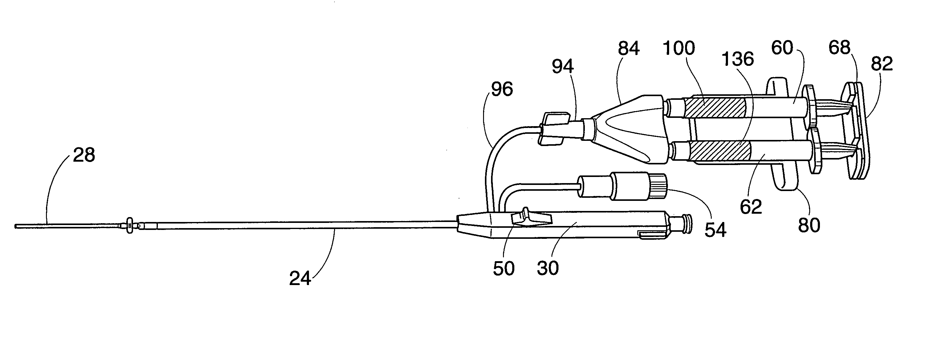
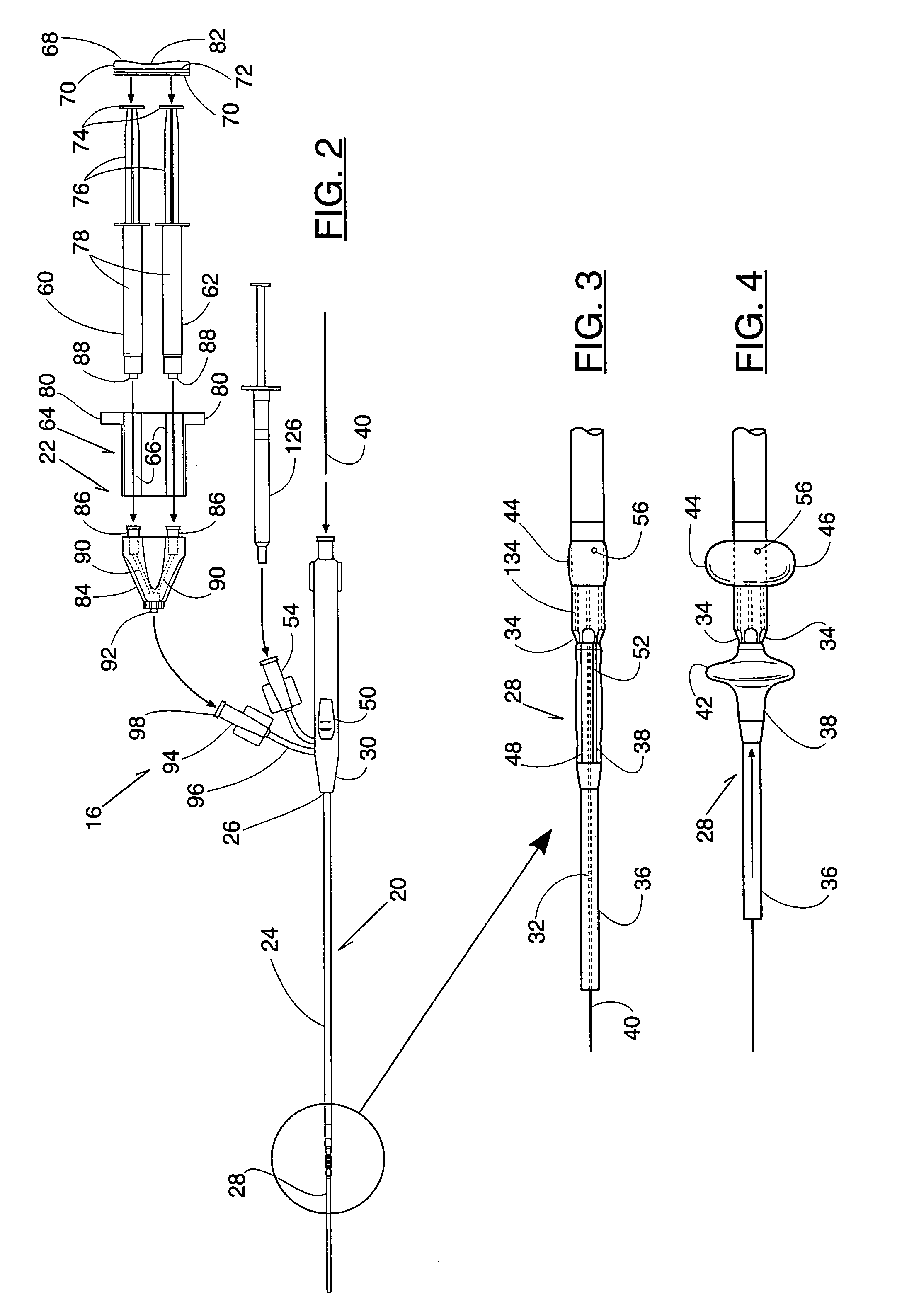
[0128]Dispensing syringes containing 2.0 mL of the polymer solution and 2.0 mL of albumin solution were connected to the joiner 84, to which a spray head was coupled. The solutions were sprayed into a polystyrene weigh boat. A cross-linked barrier network formed at room temperature in about 90 seconds.

example 2

Control of the Rate of Gelation

[0129]The rate of formation of the cross-linked barrier network of 4-PEG-SG and albumin (i.e., gelation) can be controlled by the pH of the reactive solution. To increase the rate of cross-linking, the pH of the solution is increased, and conversely, to decrease the rate of cross-linking, the pH of the solution is decreased. The pH of the solution is controlled by both the buffer strength and buffer pH.

[0130]Table 1 shows the effect of buffer strength on the rate of gelation of 17% w / w 4-PEG-SG in water for injection and 25% human serum albumin, USP at room temperature. The rate of gelation can also be controlled by adjusting the pH of the buffer at a constant buffer concentration. The buffer was placed in the solution of albumin. The gelation time is the amount of time required for the formulation to transform from the liquid state to the cross-linked solid state.

[0131]

TABLE 1Effect of Buffer Strength andBuffer pH on Gel FormationBufferConcentrationBu...

example 3

Channel-Mixing

[0132]A solution of 4-PEG-SG was prepared by dissolving 0.40g in 2.0 mL of water. The albumin solution consists 25% human serum albumin, USP (Plasbumin-25, Bayer Corporation), buffered to pH 9.0.

[0133]Syringes containing 2.0 mL of the polymer solution and albumin solution were connected to the joiner 84. A cannula channel having an inside diameter of 1 mm and a length of 20 cm was attached to the outlet port 92 of the joiner 84. The solutions were expressed through the cannula channel into a polystyrene weigh boat.

[0134]The barrier network formed at room temperature in about 20 seconds. Qualitatively, the mechanical properties of the barrier network when sprayed (as in Example 1) and the barrier network when expressed through the cannula channel were equivalent.

[0135]This demonstrates that the barrier network can be formed by channel-mixing the liquid components, without static mixing, by delivery through a small diameter channel.

[0136]III. Puncture Site Closure Using ...


PUM

PropertyMeasurementUnit
Molar densityaaaaaaaaaa

Abstract

A delivery device applies a biocompatible and biodegradable barrier material to a tissue region, e.g., to seal a vascular puncture site. The material comprises two liquid components, which are pre-packaged in individual dispensers. Upon mixing, the liquid components cross-link to create a barrier matrix. A holder attaches to the delivery device. The holder mutually supports the first and second dispensers while the protein solution and polymer solution are conveyed from the dispensers into a fluid delivery channel. The protein and polymer solutions mix as a result of flow through the channel.

Description

[0001]This application is a continuation of application Ser. No. 09 / 187,384, filed 6 Nov. 1998, now abandoned. This application is also a continuation-in-part of application Ser. No. 09 / 140,017, filed 26 Aug. 1998, now U.S. Pat. No. 6,475,182.FIELD OF THE INVENTION[0002]The invention generally relates to the application of barrier materials in a tissue region, e.g., to close vascular puncture sites in humans and other animals.BACKGROUND OF THE INVENTION[0003]There are over seven million diagnostic and therapeutic coronary interventions performed each year. By far, the majority of these interventions are performed using percutaneous puncture of the femoral artery to gain access to the arterial system.[0004]Once the intervention is concluded, the vascular puncture site has to be sealed to prevent bleeding, while natural healing processes close the puncture site. Conventional management of the puncture site has typically involved external compression using, e.g., digital pressure, C-cl...

Claims


Application Information

Patent Timeline
IPC IPC(8): A61M37/00A61B17/00
CPCA61B17/00491A61B17/0057A61L24/043A61B19/026C08L89/00C08L71/02A61L2430/36A61B2017/22069A61B2017/00495A61B2017/00637A61B2017/0065A61B2017/00654A61B2017/00672A61B50/30
Inventor CRUISE, GREGORY MHNOJEWYJ, OLEXANDER
Owner NEOMEND INC
Why Eureka
Try Eureka