Power line communication system

a technology of communication system and power line, applied in the field of data communication system, can solve problems such as the inability of each transceiver to communica

Inactive Publication Date: 2006-02-07
MAIN NET COMM
View PDF22 Cites 93 Cited by
  • Summary
  • Abstract
  • Description
  • Claims
  • Application Information

AI Technical Summary

Benefits of technology

[0011]It is an object of some aspects of the present invention to provide a meth

Problems solved by technology

However, each transceiver is unable to communicate, because of attenuation of the data communicati

Method used


Image

  • Power line communication system
  • Power line communication system
  • Power line communication system

Examples


Embodiment Construction

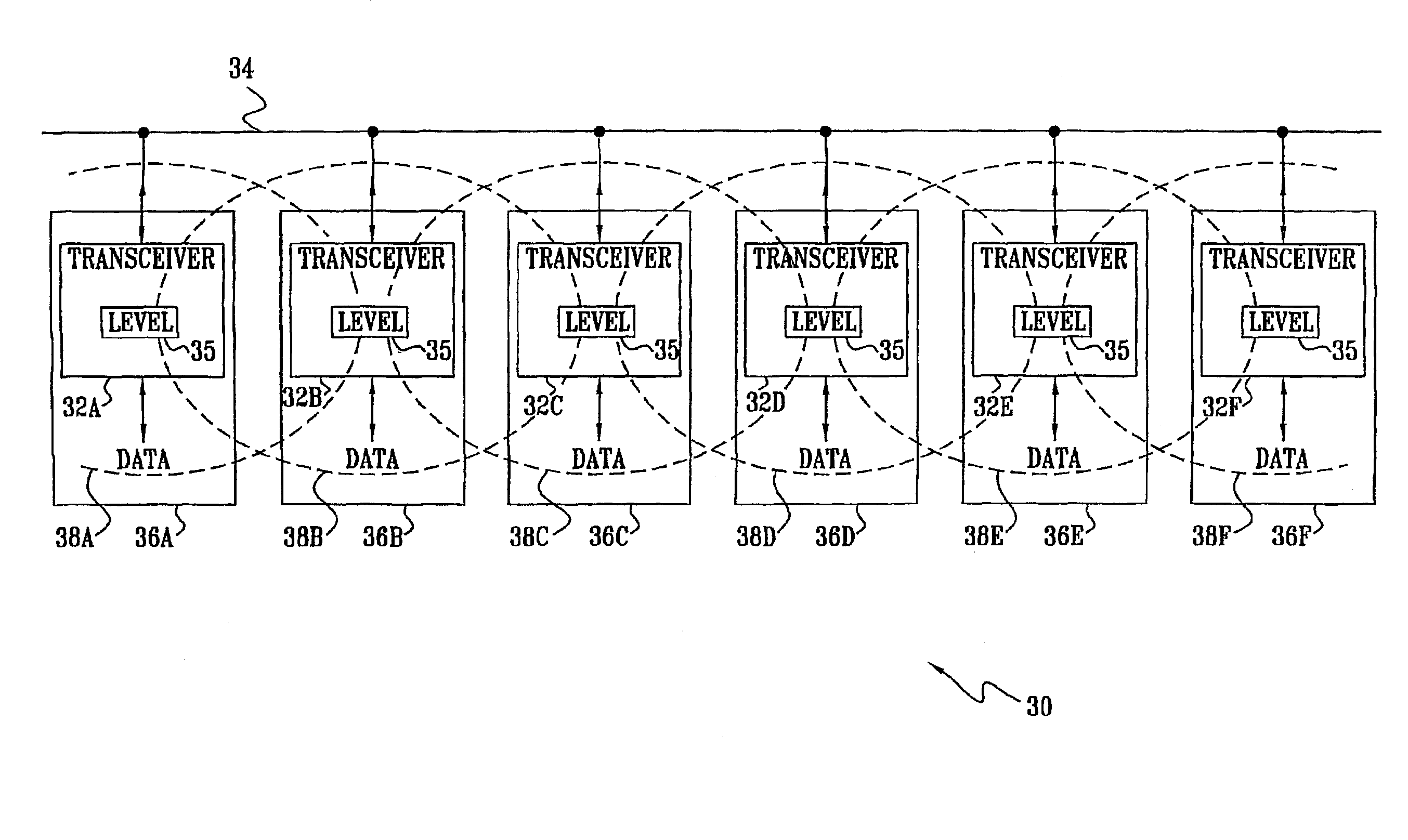
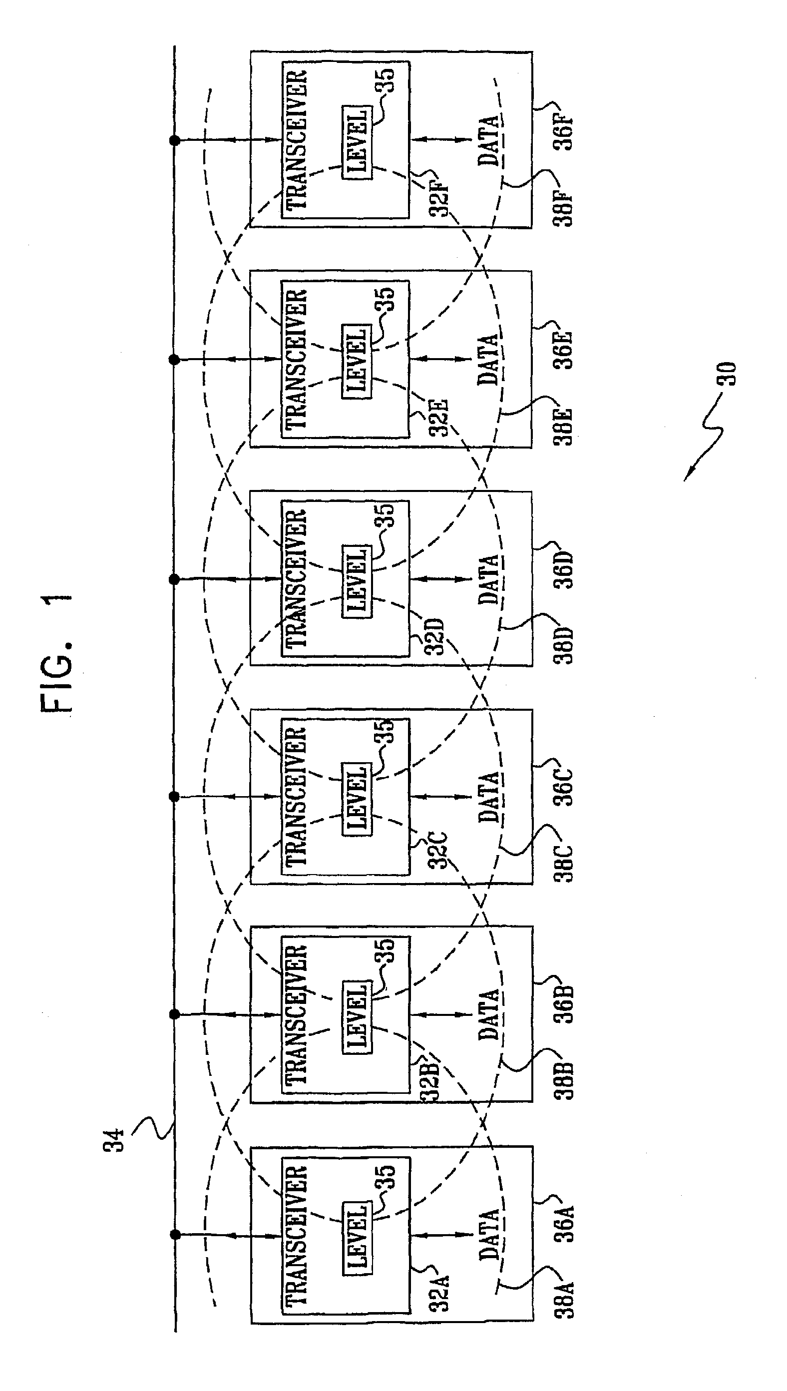
[0163]Reference is now made to FIG. 1, which is a schematic diagram of an electric power line communication network system 30, according to a preferred embodiment of the present invention. System 30 comprises a plurality of generally similar data transceivers 32A, 32B, 32C, 32D, 32E, and 32F, herein also referred to collectively as transceivers 32, each of which transceivers is coupled to a power line 34. Power line 34 preferably comprises a network of power lines supplying mains voltage, typically at a level of 120 VAC or 240 VAC, although it will be appreciated that the scope of the present invention is not limited to a specific level or type of line voltage. Preferably, power line 34 supplies line voltage to a group of locations 36A, 36B, 36C, 36D, 36E, and 36F, herein also referred to collectively as locations 36, wherein each transceiver 32 is respectively sited. Alternatively, at least some transceivers 32 are coupled to power line 34 external to locations 36. Locations 36 pre...


PUM


Abstract

A method for communication over a network of power lines (34), including establishing a communication link within a selected frequency band over the network between a first transceiver (32B) coupled to the network and a second transceiver (32C) coupled to the network. The method further includes transmitting a first signal over the link from the first transceiver to the second transceiver at a transmission power level that is sufficiently strong that the signal can be decoded by the second transceiver, but is attenuated sufficiently when it reaches a third transceiver (32E) coupled to the network so that the third transceiver can receive a second signal over the network in the selected frequency band substantially without interference by the first signal.

Description

RELATED APPLICATIONS[0001]This application is a U.S. national filing of PCT Application No. PCT / IL01 / 00745, filed Aug. 12, 2001. This application also claims the benefit of U.S. Provisional Patent Application 60 / 224,900, filed Aug. 14, 2000, which is incorporated herein by reference.FIELD OF THE INVENTION[0002]The present invention relates generally to data communication systems, and specifically to data communication systems using power lines as a medium for the communication.BACKGROUND OF THE INVENTION[0003]Data communications using residential power lines are known in the art. An advantage of using the lines is that only peripheral infrastructure needs to be added to the existing power lines in order to transmit and receive the data communications. Amongst disadvantages of using power lines are the relatively considerable interference existing on the lines, such as voltage spikes and Gaussian white and colored noise, and the need to avoid introducing radio-frequency (RF) interfer...

Claims


Application Information

Patent Timeline
IPC IPC(8): H04M11/04H04B3/54H04L12/28
CPCH04B3/54H04L12/2801H04B2203/5408H04B2203/5437H04B2203/545H04B2203/5466H04B2203/5483H04B2203/5445
Inventor ZALITZKY, YESHAYAHUKERET, JACOBEFRATI, OFIR
Owner MAIN NET COMM
Why Eureka
Try Eureka