PMD emulation, measurement and compensation device

a compensation device and emulation technology, applied in the direction of transmission, optical properties testing, structural/machine measurement, etc., can solve the problems of only promising electronic correction of “optical problems” and incompleteness of known pmd compensators, and achieve the effect of simple adjustmentability

Inactive Publication Date: 2006-02-07
THORLABS INC
View PDF14 Cites 13 Cited by
  • Summary
  • Abstract
  • Description
  • Claims
  • Application Information

AI Technical Summary

Benefits of technology

[0036]Accordingly the present invention provides a PMD emulation, measurement and compensation device which reproduces as accurately as possible the polarization transmission behavior of an optical transmission line with simple adjustability.
[0038]Moreover, it is the object of the present invention to propose a measurement device for measuring a polarization mode dispersion (PMD)-related distortion of an optical signal which allows a fast and accurate detection of the PMD of an optical transmission line.
[0040]Finally, it is the object of the present invention to specify a compensation device for compensating polarization mode dispersion (PMD)-related distortions in an optical transmission system which uses a control device that allows a fast and safe correction of PMD-related signal distortions.

Problems solved by technology

What is problematic about this is the fact that, for manufacturing reasons, the optical fibers are never fully isotropic, but can exhibit a weak, particularly geometrically caused double refraction.
While PMD still constitutes a relatively small disturbing influence in optical fiber transmission systems with a transfer rate of 2.5 Gbit / s, it is a serious problem for modern 10 Gbit / s systems, and particularly for future 40 Gbit / s systems, which has a lasting adverse effect on the bit error rate.
It has been shown, however, that the correction of the “optical problem” at the electronic level is only promising to a limited extent.
Known PMD compensators are either incomplete because the type of the targeted control is not clarified, have a high level of optical and electronic components, or do not function satisfactorily.
A reason for this is on the one hand that in the past there was no measurement device available for PMD-related distortions designed sufficiently fast and sufficiently simple.
Also, no emulator is known which can reproduce—with an acceptable adjustment expense—exactly the PMD of a real transmission line.
Instead, a low direction-dependency of the refractive index, for example as a result of mechanical deformation of the SMF, is unavoidable in practice.
At the receiver the light components therefore arrive time-delayed with respect to one another; this transit time effect leads to a broadening of the received signal and thus to an impairment of the transmission quality.
This can particularly lead to an increase in the bit error rate.

Method used


Image

  • PMD emulation, measurement and compensation device
  • PMD emulation, measurement and compensation device
  • PMD emulation, measurement and compensation device

Examples


second embodiment

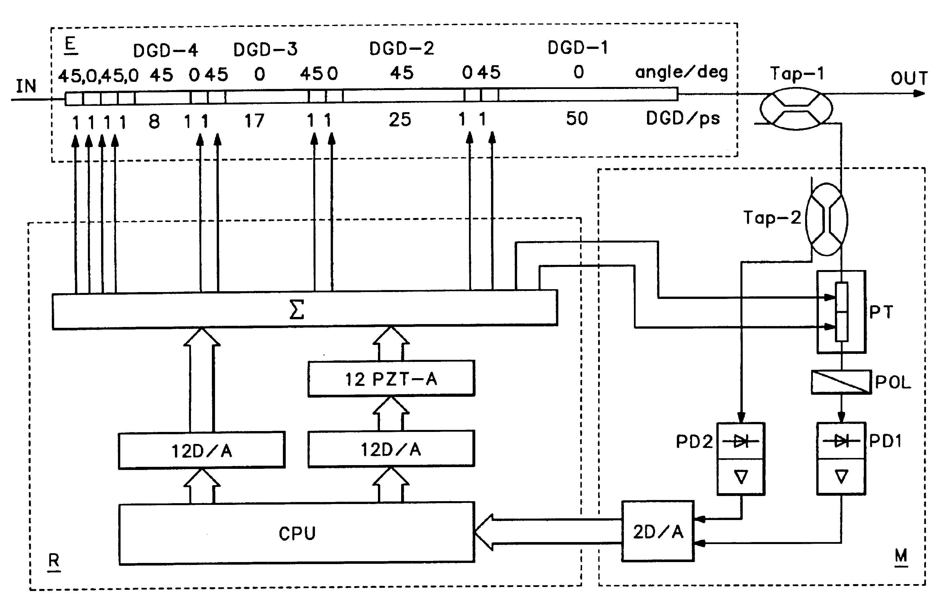
[0087] shown in FIG. 2, a second double refracting DGD element is arranged between the emulator input and the polarization transformation element. An emulation device designed this way allows in a most simple fashion the emulation of an optical transmission line with a variable DGD. The polarization element arranged between the two DGD elements with a predetermined and / or predeterminable DGD is capable of linking the input PSP of the first DGD element positioned downstream in the signal path with the output PSP of the second DGD element positioned upstream in the signal path in such a way that—depending on the adjustment of the polarization transformation element—in the one case the sum of the DGDs of the first and the second DGD element and in the other case the difference of the two DGD element results. Owing to the continuous transition from the summation point to the substraction point, all intermediate values may be set.

[0088]It is especially preferred to select the angle betwe...

first embodiment

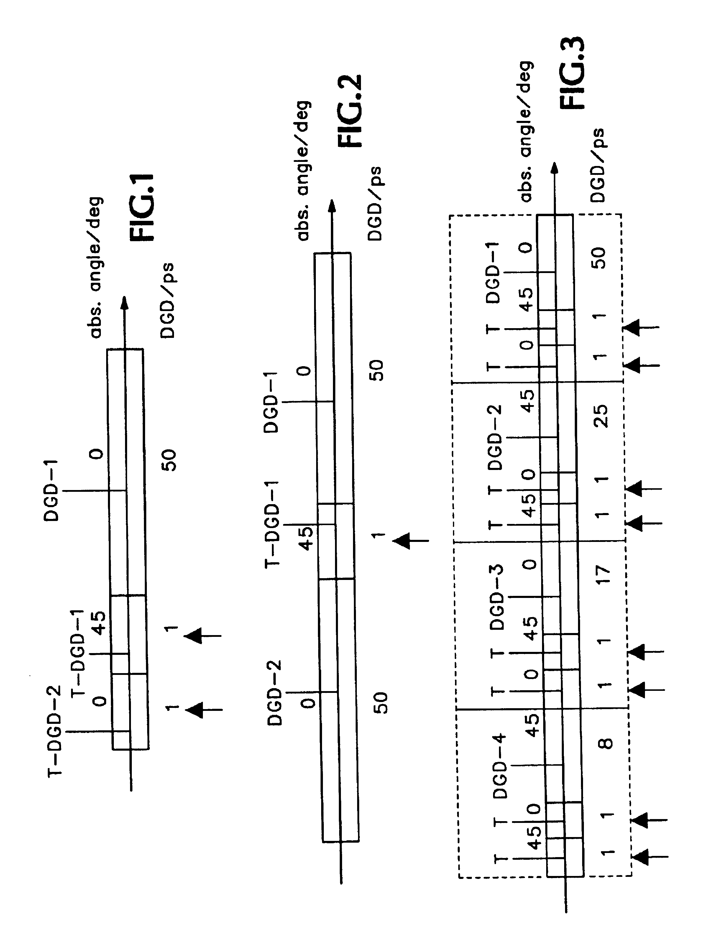
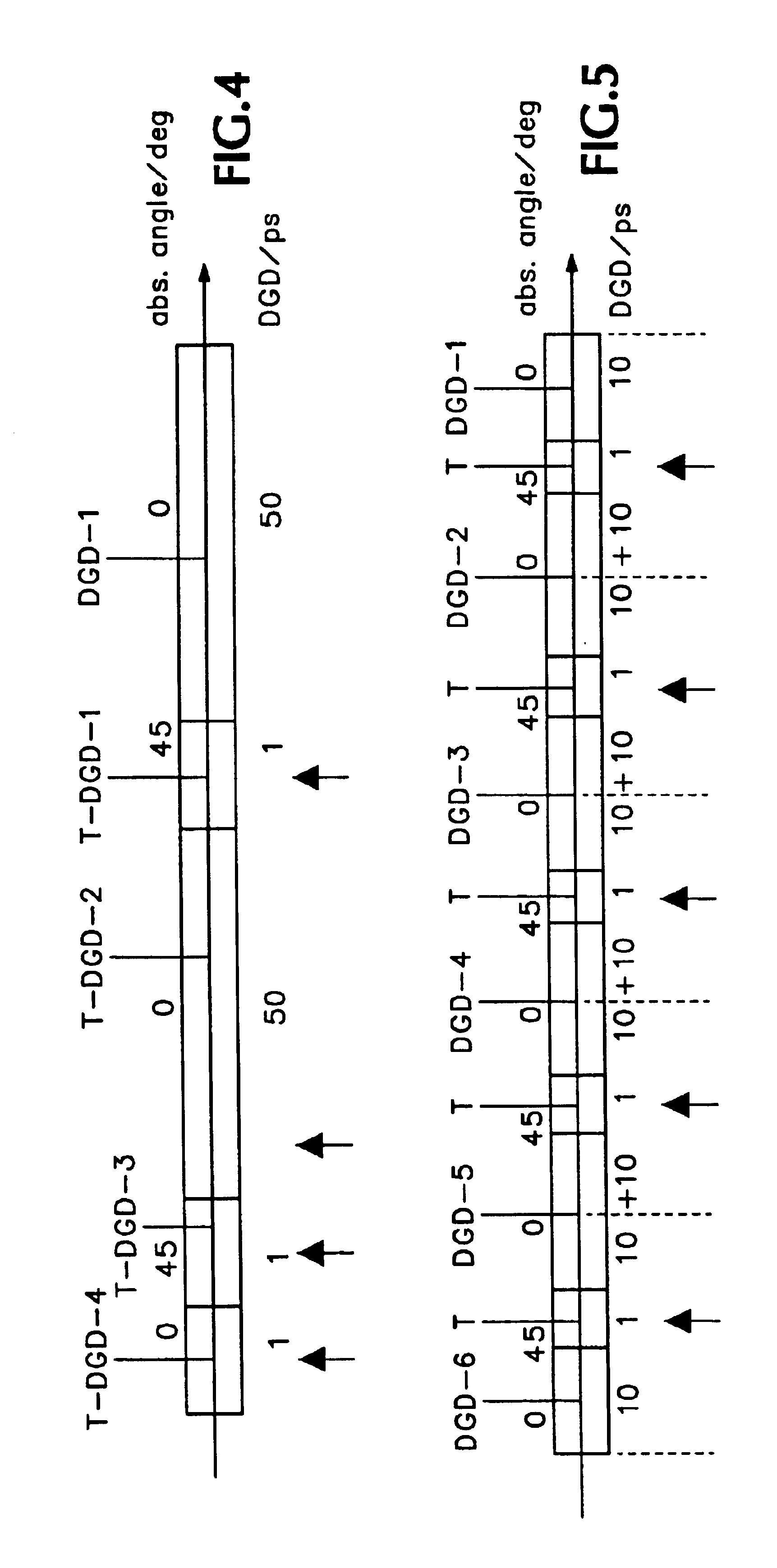
[0133]FIG. 1 shows the emulation device which allows the emulation of a transmission line with a predetermined DGD and an adjustable PSP. The emulation device exhibits one long and two comparatively short PMF pieces. The long PMF piece DGD-1 is the DGD element, which exhibits a DGD of 50 ps, for example. The short PMF pieces T-DGD-1 and T-DGD-2 only exhibit DGDs of approximately one ps each, but are each equipped with an “influential element ” via which the DGDs of T-DGD-1 and T-DGD-2 are modified in a targeted way. Influential elements used may be, for example, mechanical adjustment elements, preferably fiber squeezers and / or stretchers. Owing to the variable DGD of T-DGD-1 and T-DGD-2, they act as polarization transformation elements. In FIG. 1 (and the following figures) the “influential elements” which represent exactly one polarization transformation degree of freedom are shown schematically by arrows pointing upwards below the PMF sections.

[0134]In FIG. 1 the DGD element DGD-1...


PUM


Abstract

A PMD emulation, measurement and compensation device is based upon an emulation device having a piece of fiber having a fixed differential group delay (DGD) and another short piece of fiber (or double refracting crystal) having a variable differential group delay (T-DGD). The two pieces of fiber are coupled with a non-zero torsional angle between their respective double refractive axes, preferably 45°. A fiber squeezer / stretcher is used to provide the variable DGD for the short piece of fiber. Various serial couplings of DGD and T-DGD fiber may be added to provide greater control and accuracy, with the torsional angles preferably alternating. Such an emulation device may be incorporated into a measurement device to measure the PMD-related distortion of an optical signal. Further the measurement device may be used in a PMD compensator where an emulation device in series with the optical signal path is controlled until the measured PMD in the PMD-related distorted optical signal is minimized.

Description

CROSS-REFERENCE TO RELATED APPLICATIONS[0001]This application is a national stage entry of PCT / EP01 / 10794 filed on Sep. 18, 2001.BACKGROUND OF THE INVENTION[0002]The present invention relates to optical parametric testing, and more particularly to an emulation device for emulating a polarization mode dispersion (PMD) of an optical transmission system, a compensation device using such an emulation device, a measurement device for measuring a polarization mode dispersion (PMD)-related distortion of an optical signal, a compensation device using such a measurement device and a compensation device for compensating polarization mode dispersion (PMD)-related distortions in an optical transmission system.[0003]Over the last decade, optical waveguides (glass fibers) have been increasingly used for the transmission of digital data streams. When data transmission is to be realized over a long transmission distance, so-called single-mode fibers (SMF) with low absorption coefficients are typica...

Claims


Application Information

Patent Timeline
Patent Type & Authority Patents(United States)
IPC IPC(8): G02B6/00G01M11/02H04B10/2569
CPCH04B10/2569G01M11/336
Inventor KRAUSE, EGBERTBANDEMER, ADALBERT
Owner THORLABS INC
Why Eureka
Try Eureka