

Electromagnetic clutch device
- Summary
- Abstract
- Description
- Claims
- Application Information
AI Technical Summary
Benefits of technology
Problems solved by technology
Method used
Image

Examples
first embodiment
[0028](First Embodiment)
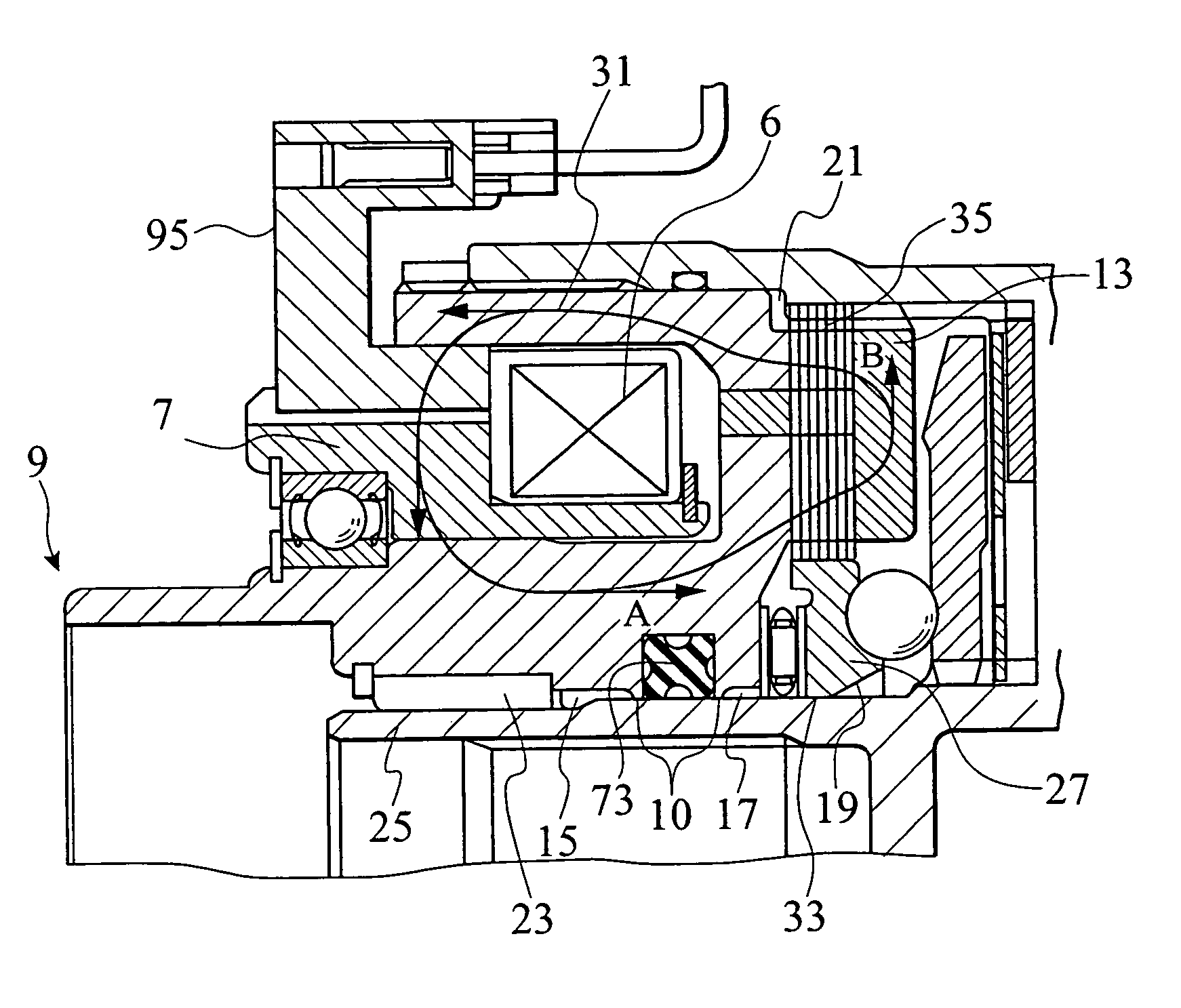
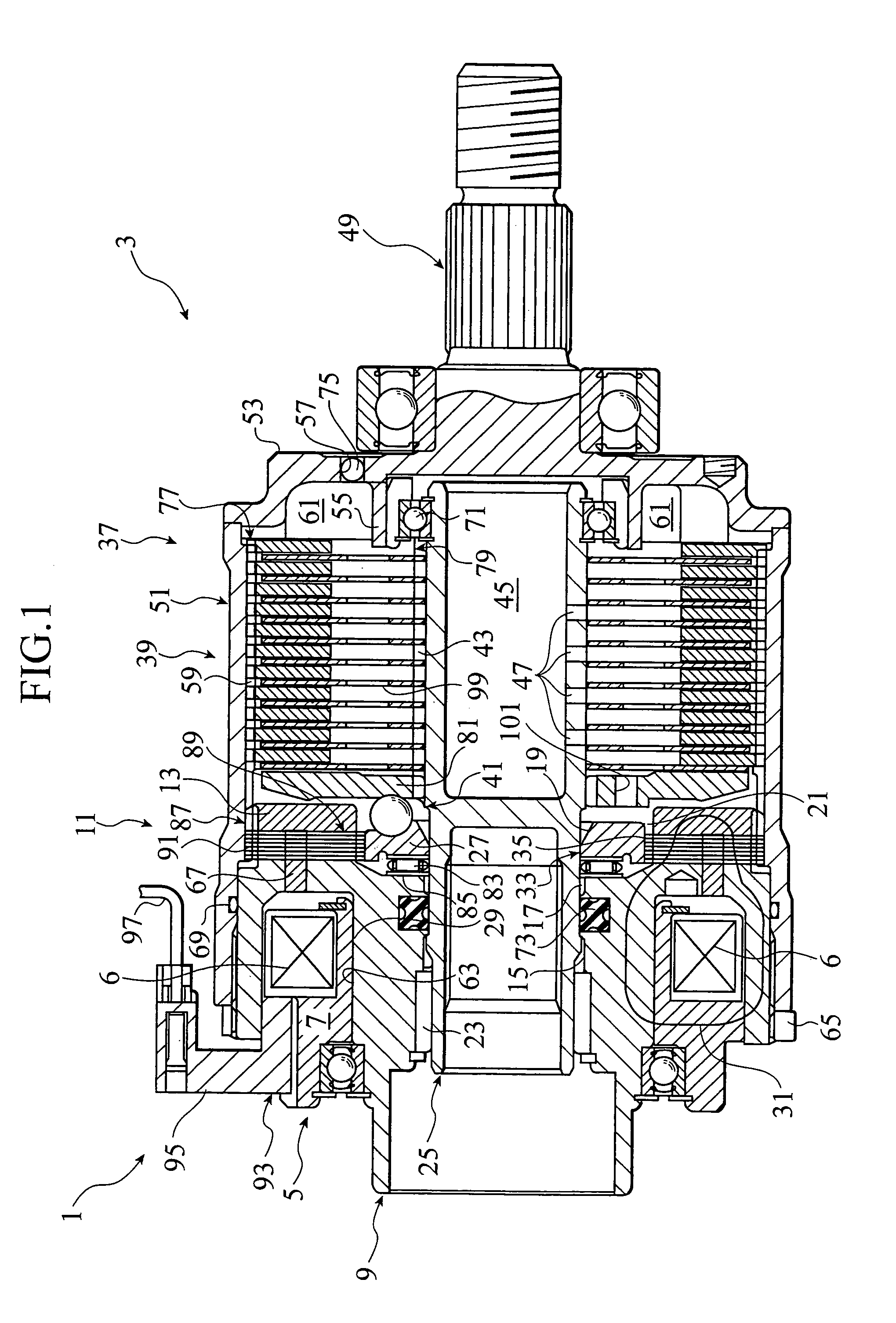
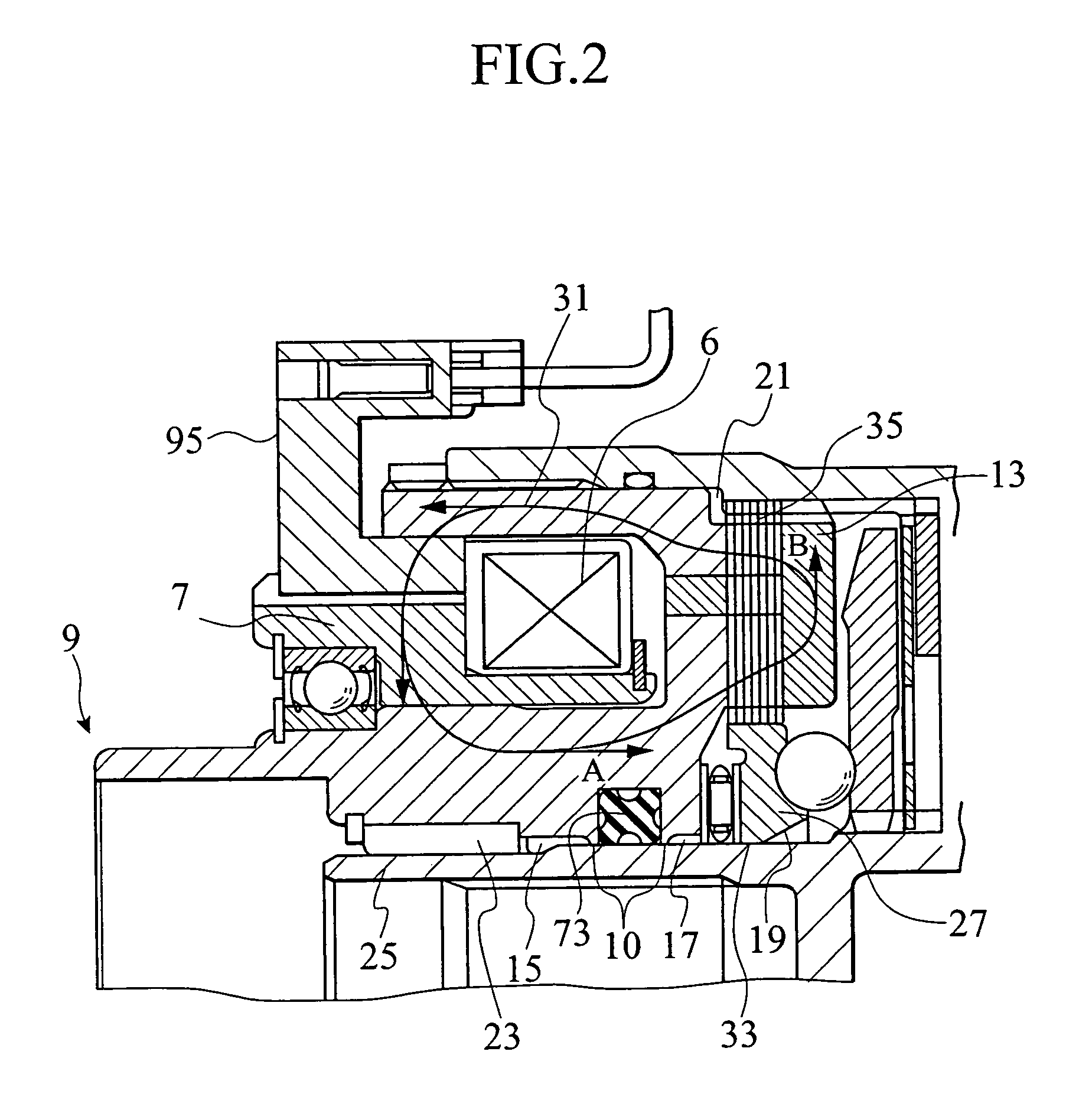
[0029]Initially, a first embodiment of the present invention is described with reference to FIGS. 1 and 2. FIG. 1 is a cross sectional view of a power coupling and uncoupling device (electromagnetic coupling) 3 incorporating an electromagnetic clutch 1 of the first embodiment. FIG. 2 is an enlarged view illustrating an essential part of the first embodiment. Also, by the term “a left and right direction” is meant the left and right direction of the vehicle, and the right side in FIG. 1 corresponds to a front (closer to an engine) of a four-wheeled vehicle. Also, component elements with no reference numerals are not shown.
[0030]This power system is comprised of an engine (prime mover), a transmission, a transfer, a front def (differential unit by which a drive power of the engine is split to left and right front wheels), a front axle, left and right front wheels, a front propeller shaft, the power coupling and uncoupling device 3, a rear propeller shaft, a rea...
second embodiment
[0076](Second Embodiment)
[0077]Next, referring to FIGS. 3 to 5, a second embodiment of the present invention is described. FIG. 3 is a cross sectional view of a power coupling and uncoupling device 100 incorporating an electromagnetic clutch 900, FIG. 4 is a cross sectional view showing a splined section 550 of electromagnetic clutch 900, and FIG. 5 is a graph illustrating a varying characteristic of a transfer torque in terms of excitation current of an electromagnetic coil 490.
[0078][Structure of Power Coupling and Uncoupling device 100]
[0079]As shown in FIG. 3, the power coupling and uncoupling device 100 is comprised of a rotary case 300 (proximate (rotary) member) serving as an input member, a connecting shaft 500 (proximate member) serving as an output member to which a rotational drive power of the rotary case 300 is delivered, a multi-plate type main clutch 700 disposed between the rotary case 300 and the connecting shaft 500 to allow the rotational drive power of the rotary...
third embodiment
[0108](Third Embodiment)
[0109]Next, an electromagnetic clutch device of a third embodiment of the present invention is described with reference to FIG. 6. The electromagnetic clutch 900 of the third embodiment contemplates to have, in addition to the non-teeth portions 590 (serving as the magnetic flux leakage eliminating means (magnetic flux leakage eliminating section)) formed between the adjacent spline teeth 470a of the armature 470, the rotary case 300 formed with circumferentially spaced tooth-cut-out portions 950 (serving as magnetic flux leakage eliminating means (magnetic flux leakage eliminating section)) formed between the adjacent spline teeth 250a of the rotary case 300, thereby providing an extremely widened air gap 970 between the rotary case 300 and the armature 470.
[0110]With the electromagnetic clutch device 900 of the third embodiment, as set forth above, the provision of the tooth-cut-out portions 950 formed adjacent to teeth portions 250a on the inner periphery ...
PUM
 Abstract
Description
Claims
Application Information