
Fine carbon fiber and method for producing the same

a carbon fiber and carbon fiber technology, applied in the field of fine carbon fiber, can solve the problems of disadvantageous decrease in workability and mechanical properties of obtained composite materials, carbon fiber cannot have electrical conductivity comparable to metal, and the ratio of length to diameter is limited, so as to achieve good adhesive properties and high electrical conductivity

Inactive Publication Date: 2006-02-14
SHOWA DENKO KK
View PDF9 Cites 1 Cited by
  • Summary
  • Abstract
  • Description
  • Claims
  • Application Information

AI Technical Summary

Benefits of technology

[0021]An object of the present invention is to provide a fine carbon fiber capable of serving as a filler material having high electrical conductivity and a diameter of less than 400 nm, preferably from 2 to 300 nm, and exhibiting good adhesive property to resin or the like.
[0023]Another object of the present invention is to provide a chemically and thermally stable field emission material having an excellent electron emission property and a long life.

Problems solved by technology

However, the organic fiber used as the starting material of this carbon fiber has a diameter of approximately from 5 to 10 μm and therefore, the produced carbon fiber cannot have a small diameter and is limited in the ratio of length to diameter (i.e., aspect ratio).
However, even by graphitization, the carbon fiber cannot have electrical conductivity comparable to metal.
If the amount of carbon fiber blended is increased to compensate for this insufficient electrical conductivity, the obtained composite material disadvantageously decreases in workability and mechanical properties.
However, the production process by this method involves many steps and although the carbon fiber used for the electron emitting part is conventionally processed to have a needle-like tip using Mo or the like, the chemical stability and the thermal stability are not sufficiently high as an electron emitting material of a display.
However, on a mass-production scale, VGCF having a small diameter of less than 100 nm cannot be produced.
This method using arc discharge is, however, not suitable for mass-production and not implemented in practice.
These carbon fibers all have a smooth surface, and therefore, are poor in adhesive property, wettability and affinity, and when used as a composite material, the surface of the carbon fiber must be treated, for example, by thorough oxidation.

Method used


Image

  • Fine carbon fiber and method for producing the same
  • Fine carbon fiber and method for producing the same
  • Fine carbon fiber and method for producing the same

Examples


example

[0078]The present invention is described in greater detail below by referring to the Example, which is not intended to limit the scope of the present invention and should not be construed as doing so. Unless indicated otherwise herein, all parts, percents, ratios and the like are by mass.

[0079]As shown in the schematic view of FIG. 5, a starting material feed pipe 4 for feeding a starting material vaporized in a starting material vaporizer 5, and a carrier gas feed pipe 6 were connected to the top of a vertical heating furnace 1 (inner diameter: 170 mm, length: 1,500 mm). The vertical heating furnace 1 is provided with one or more heaters 2 for heating the furnace and with a starting material recovery system 3.

[0080]A toluene solution having dissolved therein 3% by mass of ferrocene and 1% by mass of thiophene was vaporized and fed through the starting material feed pipe 4 at a rate of 20 g / min and hydrogen as a carrier gas was fed at a rate of 75 l / min, thereby performing the react...


PUM

PropertyMeasurementUnit
Diameteraaaaaaaaaa
Structureaaaaaaaaaa
Aspect ratioaaaaaaaaaa

Abstract

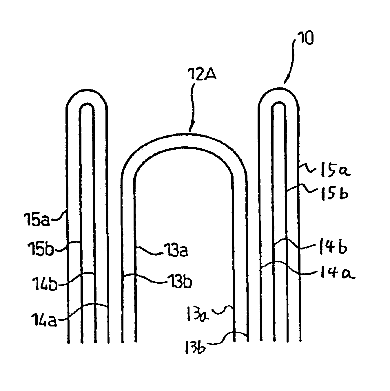
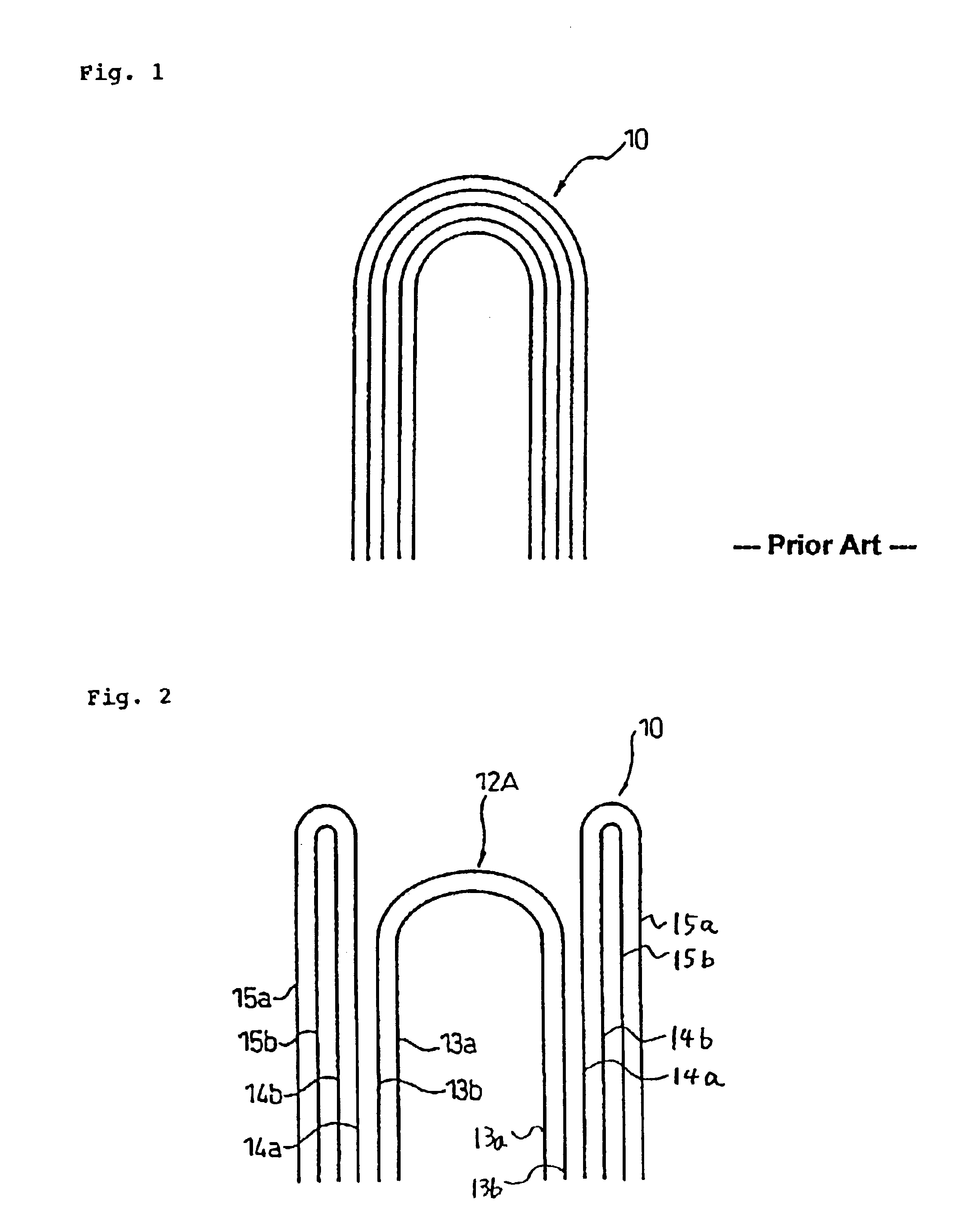
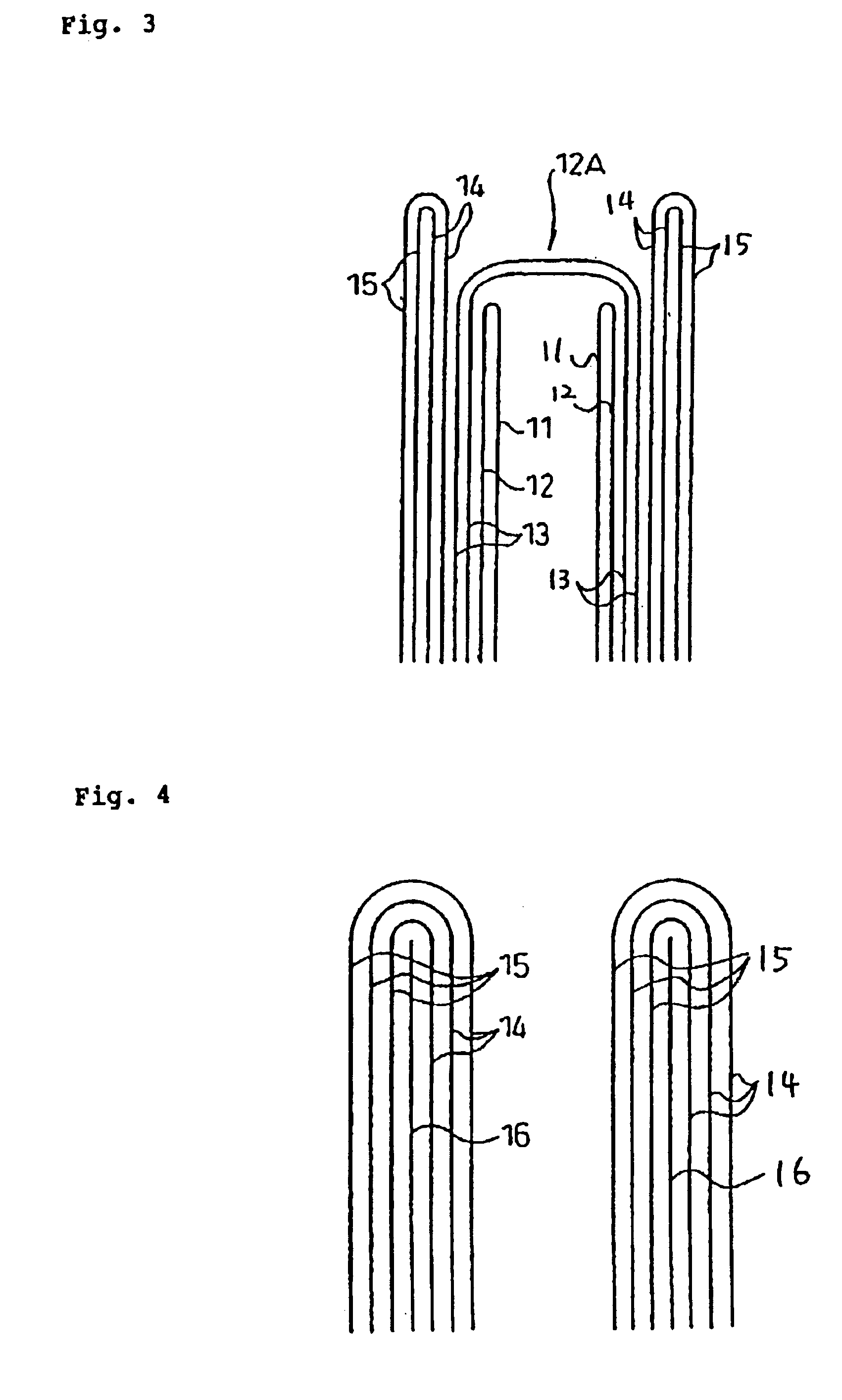
A fine carbon fiber having a multilayer structure having stacked cylindrical carbon sheets and a center axis having a hollow structure. The fine carbon fiber has an outer diameter of 2 to 300 nm and an aspect ratio of 10 to 15,000, and at least one cylindrical carbon sheet layer among the multiple layers is folded at an end part of the carbon fiber and continued to another cylindrical carbon sheet. The folded and continued cylindrical carbon sheets form a cylindrical structure opened at the end part.

Description

[0001]This is a divisional of Application No. 09 / 986,438 filed Nov. 8, 2001 U.S. Pat. No. 6,565,971, which claims benefit of Provisional Application No. 60 / 267,177 filed Feb. 8, 2001; the above noted prior applications are all hereby incorporated by reference.CROSS REFERENCE TO RELATED APPLICATIONS[0002]This application is an application filed under 35 U.S.C. §111(a) claiming benefit pursuant to 35 U.S.C. §119(e)(1) of the filing date of Provisional Application 60 / 267,177 filed Feb. 8, 2001 pursuant to 35 U.S.C. §111(b).FIELD OF THE INVENTION[0003]The present invention relates to a fine carbon fiber having a specific structure and also relates to a production process and an application of the carbon fiber. More specifically, the present invention relates to a fine carbon fiber suitable as a filler for composite materials of resin, rubber or the like, a semiconductor material, a catalyst and a field emission material, and also relates to a production process thereof.BACKGROUND OF THE...

Claims


Application Information

Patent Timeline
IPC IPC(8): B32B27/04C01B31/02D01F9/127
CPCB82Y30/00B82Y40/00C01B31/0233D01F9/127C01B2202/34Y10T428/2419Y10T428/2916Y10T428/2918Y10T428/24777C01B2202/36C01B32/162Y10T428/249927Y10T428/249933Y10T428/24994Y10T428/249924
Inventor MORITA, TOSHIOINOUE, HITOSHISUHARA, YUTAKA
Owner SHOWA DENKO KK
Learn More